
Method and apparatus for managing ultracapacitor energy storage systems for a power transmission system

a technology of energy storage system and power transmission system, which is applied in the direction of indicating/monitoring circuit, instruments, transportation and packaging, etc., can solve the problems of affecting the operation of ultracapacitor cells, affecting the operation of ultracapacitors, and unable to equalize ultracapacitors in the same way as lead-acid or other batteries

Inactive Publication Date: 2009-12-15
TENNESSEE VALLEY AUTHORITY
View PDF13 Cites 41 Cited by
  • Summary
  • Abstract
  • Description
  • Claims
  • Application Information

AI Technical Summary

Benefits of technology

The system enables precise monitoring and charging of individual ultracapacitor cells, ensuring optimal health and safety by reducing the risk of overcharge, achieving cost savings through reduced relay usage and efficient operation, and supporting dynamic reactive-power compensation in power transmission systems.

Problems solved by technology

When ultracapacitor cells are placed in series, variations in capacity, leakage current, and internal resistance can cause some cells to be overcharged while others are undercharged.
This can result in conditions that are detrimental to the operation of ultracapacitor cells.
Therefore, ultracapacitors must be equalized through some external means.Ultracapacitors cannot be equalized in the same way as lead-acid or other batteries, which are typically subjected to long periods of charging at low currents.
Doing this with an ultracapacitor would cause excessive pressure to build up within a cell (in the case of a sealed design) and electrolyte loss (in the case of a vented design).
This is acceptable for small systems, but is prohibitive in larger systems with thousands of cells.
These approaches cause inefficiency due to high power dissipation in the circuit.

Method used


Image

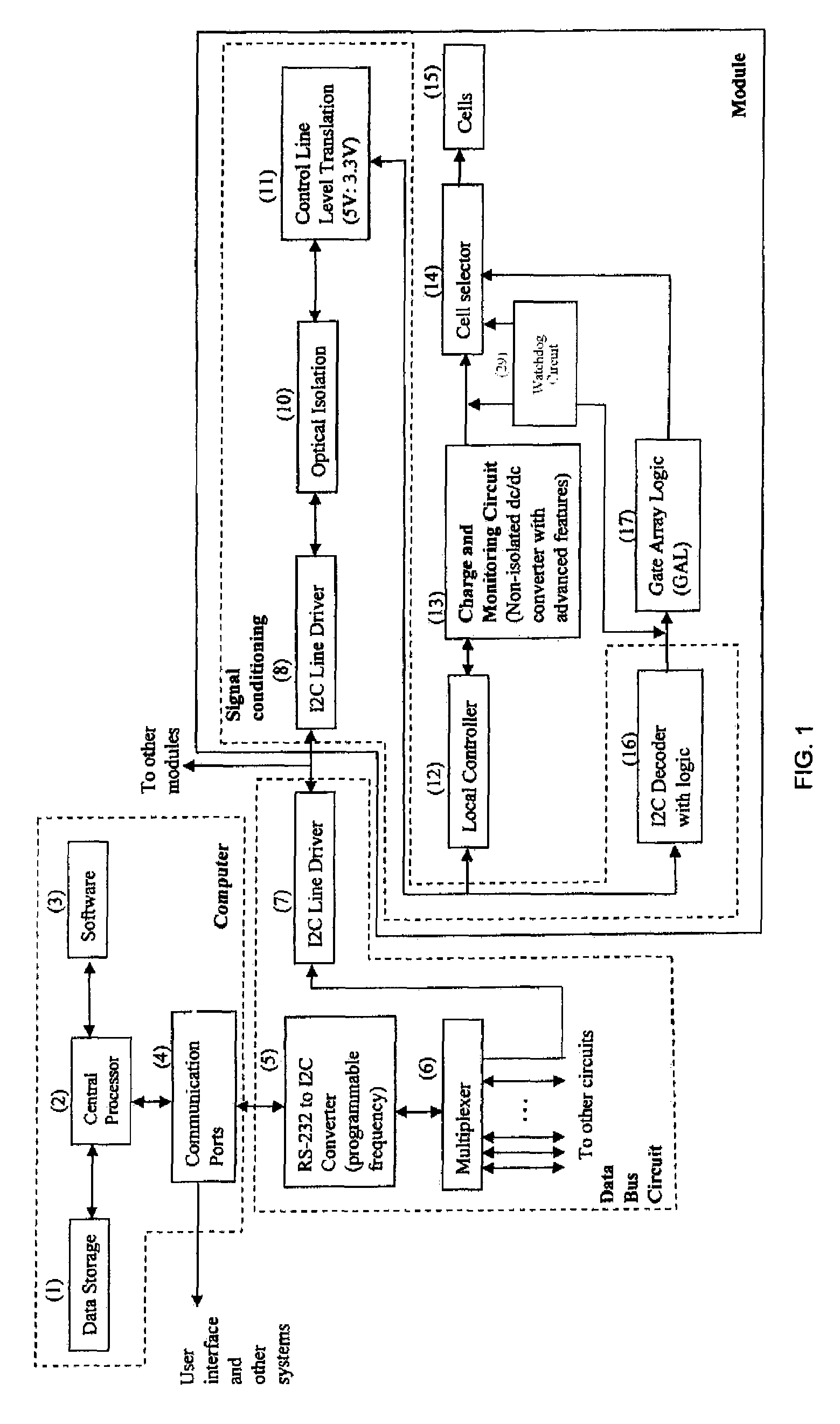
  • Method and apparatus for managing ultracapacitor energy storage systems for a power transmission system
  • Method and apparatus for managing ultracapacitor energy storage systems for a power transmission system
  • Method and apparatus for managing ultracapacitor energy storage systems for a power transmission system

Examples


Embodiment Construction

[0024]The overall purpose of the system is to automatically manage both individual cells and the series combination of cells (one or more strings) under dynamic and static conditions. The identity of multiple individual units (cells or strings) exhibiting a problem is visually prompted along with a detailed time date report on the system disk, monitor and / or printer.

[0025]FIG. 1 illustrates the overall apparatus for managing individual cells and strings according to the present invention. FIG. 2 is representative of the specific arrangement of switches for cell selection (14). The system is used in conjunction with an “external” or “main charger that is used for bulk charging of the string(s) and is not shown. Likewise, the load is not shown. As shown in (FIG. 2), a string has a plurality of cells (25, 26, 27, 28) connected electrically in series with one another by cell connectors or terminals. The terminals provide for access to each individual cell in the module. Each cell has a ...


PUM

PropertyMeasurementUnit
direct currentaaaaaaaaaa
lengthaaaaaaaaaa
voltageaaaaaaaaaa

Abstract

A method and apparatus for automatically monitoring and controlling various parameters of individual ultracapacitor cells in a series string of such cells. These parameters are monitored, and a replacement charge current is delivered to any cell which has lost charge due to discharge either external or internal to the cell. Also, the application of this method and apparatus to energy storage systems for an electrical power transmission grid.

Description

[0001]Priority is claimed from Provisional Application No. 60 / 659,067, Mar. 8, 2005 the entire disclosure of which is hereby incorporated by reference.BACKGROUND OF THE INVENTION[0002]The invention first relates to a method and apparatus for management of individual cells within an ultracapacitor-based system.[0003]The invention relates to a method and apparatus for management of individual cells within an ultracapacitor-based system.[0004]Ultracapacitors are different from batteries in the following ways:[0005]Batteries have a relatively flat discharge curve, the discharge curve for an ultracapacitor is capacitive in nature and follows the E=0.5CV2 where E is energy (in joules), C is capacitance (in farads), and V is voltage (in volts).[0006]Ultracapacitors do not exhibit the “coup-de-fouet” (a sudden drop in voltage at the beginning of discharge of a lead-acid battery), so that the equivalent series resistance (ESR) is easily determined by delta V / delta I. This is less true for a ...

Claims


Application Information

Patent Timeline
Patent Type & Authority Patents(United States)
IPC IPC(8): G01R19/00G01N27/416G01R31/02H02J7/00
CPCH02J7/0019H02J7/345H02J7/0022H02J7/0021H02J7/0014H02J7/0048H02J7/005
Inventor INGRAM, MICHAEL R.BRADSHAW, DALE T.GEIST, THOMAS D.KAMATH, HARESHMANSOOR, ARSHADNASTASI, DONIBUNTON, SCOTT
Owner TENNESSEE VALLEY AUTHORITY
Learn More