Locking device for vehicle

a technology for locking devices and vehicles, applied in anti-theft devices, lock applications, roofs, etc., can solve the problems of large proportion of manufacturing costs affecting the manufacturing cost of springs, and achieve the effect of reducing the biasing force of biasing means, reducing the manufacturing cost of locking devices for vehicles, and reducing the proportion of manufacturing costs

Inactive Publication Date: 2009-12-15
IMASEN ELECTRIC IND
View PDF11 Cites 18 Cited by
  • Summary
  • Abstract
  • Description
  • Claims
  • Application Information

AI Technical Summary

Benefits of technology

[0029]a depression controlling means (7d) for restricting the rotation of the depressing member to prevent the depression-side cam portion from depressing the tip end of the rattle-removing member, and as the lock plate rotates when the locked state between the latch-side second locking portion and the lock-side cam portion is released, allowing the depressing member to rotate in a direction in which depression to the tip end of the rattle-removing member by the depression-side cam portion is released;
[0035]Since the number of the biasing means is reduced by one, the frequency of occurrence of failure resulted from the reduction in the biasing force of the biasing means can be lowered. Further, the proportion of the manufacturing cost for the biasing means to the manufacturing cost of the locking device for vehicle can be reduced by the reduced one biasing means.

Problems solved by technology

In addition, the cost of springs account for a large proportion of the manufacturing cost.

Method used


Image

  • Locking device for vehicle
  • Locking device for vehicle
  • Locking device for vehicle

Examples


embodiment

Effect of Embodiment

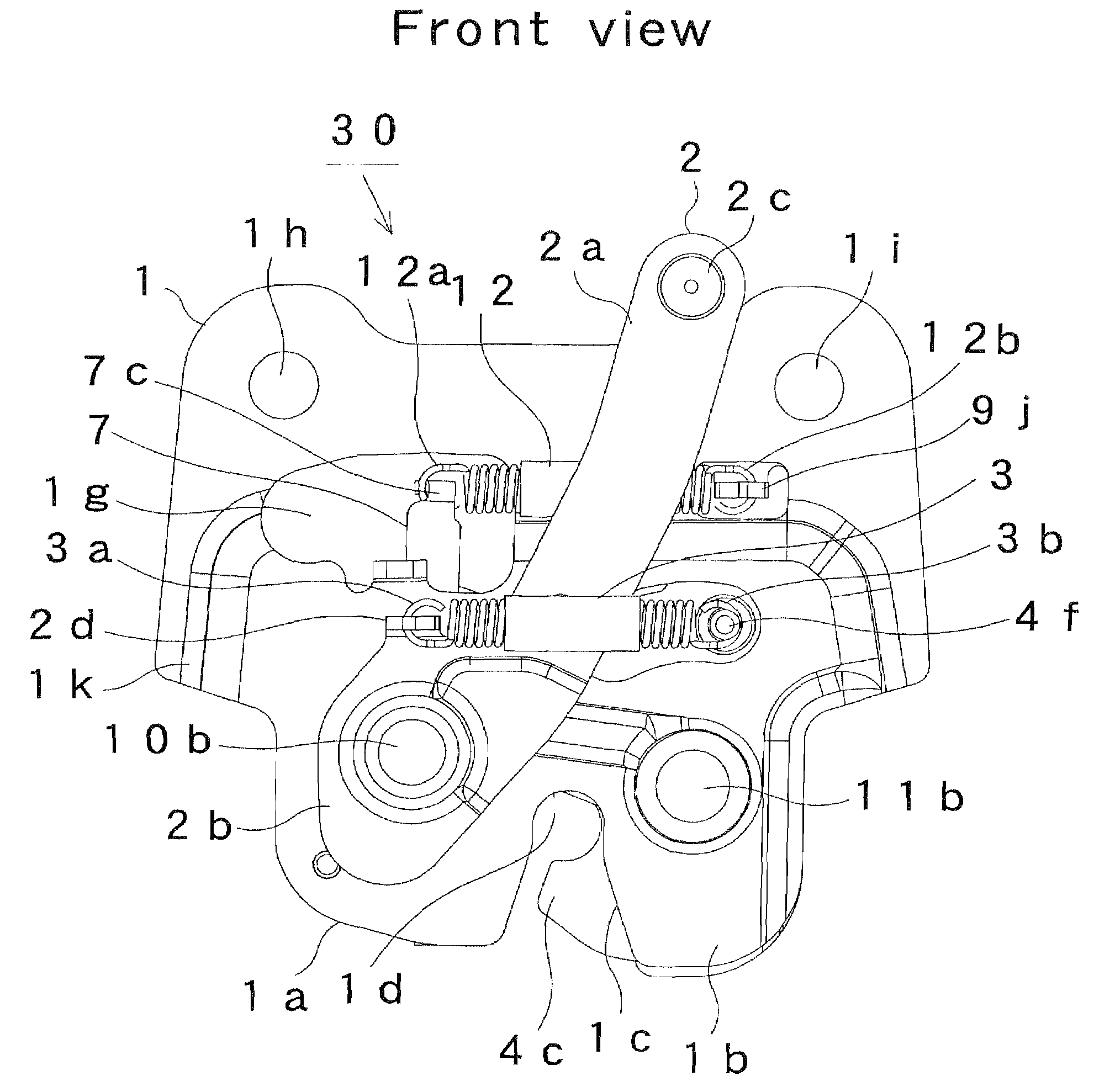
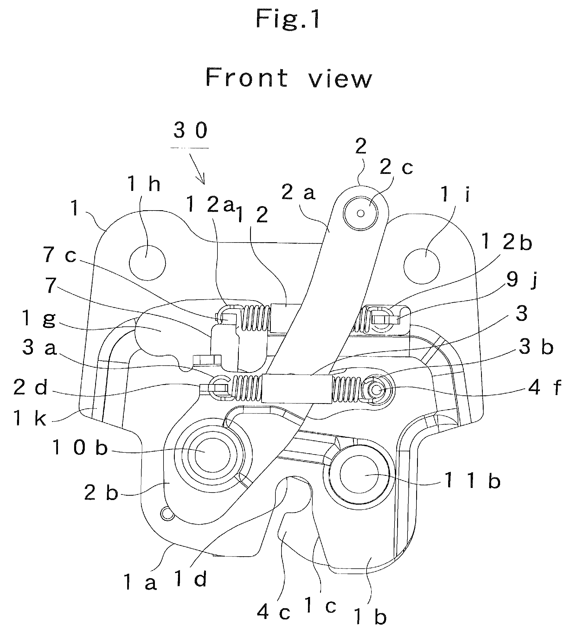
[0111](1) By practicing the locking device for vehicle 30 according to the foregoing embodiment, since the rattle removing-side recessed portion 6d of the rattle-removing plate 6 is formed into the shape that matches the peripheral surface of the striker 20, the rattle removing-side recessed portion 6d has a large area for engagement with the striker 20, and large friction arises at the engagement portion. Thus, there is no possibility that the striker 20 engaged with the rattle removing-side recessed portion 6d moves to rattle.

[0112](2) It is sufficient to provide only three pieces of biasing means in total, that is, the coil springs 3, 12, and the free rotation preventing member 8, to the locking device for vehicle 30. Thereby, the number of the biasing means can be reduced by one than the conventional device (Prior art 1).

[0113]Since the number of the biasing means is reduced by one, the frequency of occurrence of failure resulted from the reduction in the bia...


PUM


Abstract

The present invention realizes a locking device for vehicle free from the occurrence of rattle at the portion where the striker is locked. When a lock plate 5 and a latch plate 4 are brought into a locked state and a latch-side recessed portion 4d of the latch plate 4 is engaged with a striker 20, a plate pressing cam 7 rotates clockwise by a restoring force by a coil spring 12, so that its depressing-side cam portion 7e depresses a tip end 6c of a rattle-removing plate 6. A rattle removing-side recessed portion 6d of the rattle-removing plate 6 engages with the peripheral surface of the striker 20, to suppress the rattle of the striker 20. Since the rattle removing-side recessed portion 6d is formed into the shape that matches the peripheral surface of the striker 20, occurrence of rattle can be strictly suppressed.

Description

CROSS-REFERENCE TO RELATED APPLICATION[0001]The present application claims priority under 35 U.S.C. § 119 to Japanese Patent Application No. JP2006-245574. The content of the application is incorporated herein by reference.BACKGROUND OF THE INVENTION[0002]1. Field of the Invention[0003]The present invention relates to a locking device for vehicle applied as a device for locking a bottom surface of a vehicle seat with a floor of the vehicle, a device for locking a back door, and the like.[0004]2. Description of the Related Art[0005]Conventionally, as this type of locking devices for vehicle, those described in Prior art 1 and 2 are known. FIG. 9 is a diagram for illustrating a locked state of the locking device for vehicle described in Prior art 1. FIG. 10 is a diagram for illustrating a locked state of the locking device for vehicle described in Prior art 2.[0006]The locking device shown in FIG. 9 is a locking device for back door, and includes: a substrate 51 formed with a striker-...

Claims


Application Information

Patent Timeline
Patent Type & Authority Patents(United States)
IPC IPC(8): E05C3/06B60J5/10E05B83/00E05B77/36E05B83/18E05B85/24E05B85/26
CPCB60N2/01583E05B17/0045E05B77/36E05B83/16Y10S292/56Y10S292/73Y10T70/5889Y10T292/1047
Inventor SATO, YUSUKE
Owner IMASEN ELECTRIC IND
Why Eureka
Try Eureka