
Press-working method

a technology of pressing and pressing, applied in the field of pressing pressing, can solve the problems of increasing both the number of production steps and production costs, and the difficulty of machining, and achieve the effect of reducing the scale and scope of machining

Inactive Publication Date: 2009-12-08
KUBOTA CORP
View PDF15 Cites 3 Cited by
  • Summary
  • Abstract
  • Description
  • Claims
  • Application Information

AI Technical Summary

Benefits of technology

This method reduces the need for extensive machining, minimizes deformation in the thickness direction, and enhances production efficiency by allowing edges to form a predetermined shape without additional processing, thus reducing production costs and complexity.

Problems solved by technology

In this case, machining is difficult if the edges of the walls of the blank are not flat but are in a bent state, and inevitably also entails increases in both the number of production steps and the production costs.

Method used


Image

  • Press-working method
  • Press-working method
  • Press-working method

Examples


first alternative embodiment

of the Invention

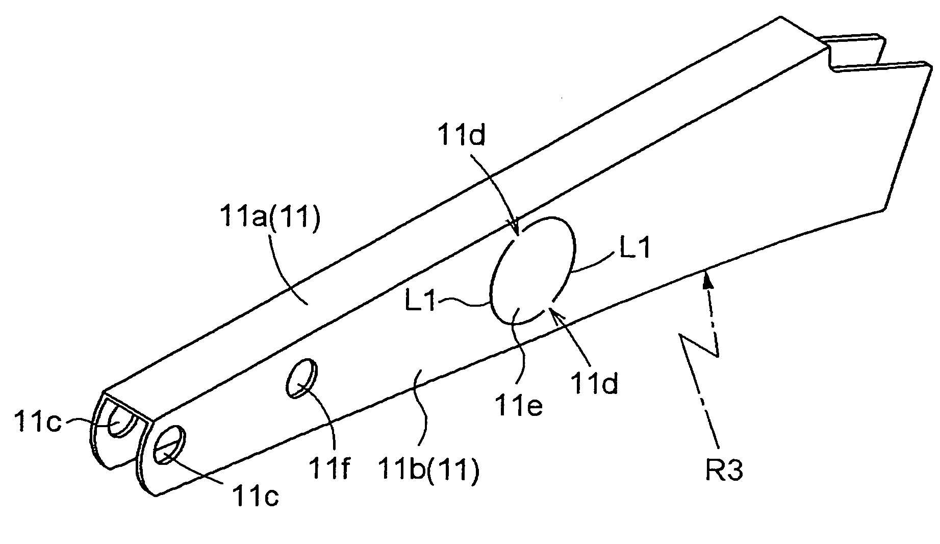
[0050]When the pair of semicircular cut-out lines L1 and the connecting part 11d of the first member 11 are formed on a portion corresponding to the opening 10 of the walls 11b of the first member 11, as shown in FIG. 6 of the above-described Detailed Description of the Preferred Embodiments, the pair of semicircular cut-out lines L1 and the connecting part 11d of the first member 11 may be formed in an elliptical shape, as shown in FIG. 14. (As shown in FIG. 14, an elliptical shape is obtained so that the vicinity of the center of the cut-out lines L1 in the walls 11b of the first member 11 has a long radius R4, and the connecting part 11d of the first member 11 has a short radius R5. The long radius R4 is set to be substantially the same as the radius of the opening 10, and the short radius R5 is set to be slightly smaller than the radius of the opening 10.)

[0051]Accordingly, as shown in FIG. 12, the vicinity of the connecting part 11d in the walls 11b of the first...

second alternate embodiment

of the Invention

[0053]When the first member 11 is bent to have a U-shaped cross section (when the first member 11 is bent so as to provide a bottom 11a and walls 11b) in the above-described First Alternate Embodiment of the Invention of the Detailed Description of the Preferred Embodiments, the first member 11 may be bent to have a U-shaped cross section so that the cross section of the bottom 11a of the first member 11 will form an arched shape and not a linear shape (see FIGS. 5A and 5B).

[0054]A configuration may be obtained wherein the cut-out lines L1 and the connecting part 11d of the first member 11 shown in FIGS. 6 and 14 are eliminated, and a narrow groove is machined in the portion corresponding to the opening 10 of the wall 11b of the first member 11. The walls 11b of the first member 11 and the blank part 11e inside the opening 10 will thereby be connected by a thin part of the bottom of the groove.

[0055]The first member 11, rather than being bent to have a U-shaped cross...


PUM

PropertyMeasurementUnit
shapeaaaaaaaaaa
angleaaaaaaaaaa
thicknessaaaaaaaaaa

Abstract

A press-working method comprises: cutting out a member with a predetermined shape from a sheet material, the member having a longitudinal direction; bending the member with the predetermined shape to form a bottom portion and a wall portion extending at an angle from the bottom portion as seen in a direction along the longitudinal direction such that the bottom portion has an arched surface as seen in a side view, using at least one plunger and at least one die, wherein an edge of the wall portion is allowed to expand along the plunger and the die while changes in a thickness of the wall portion is controlled by the plunger and the die, and wherein the step of cutting out a member is performed such that the wall portion has an edge with a preset shape after the bending step.

Description

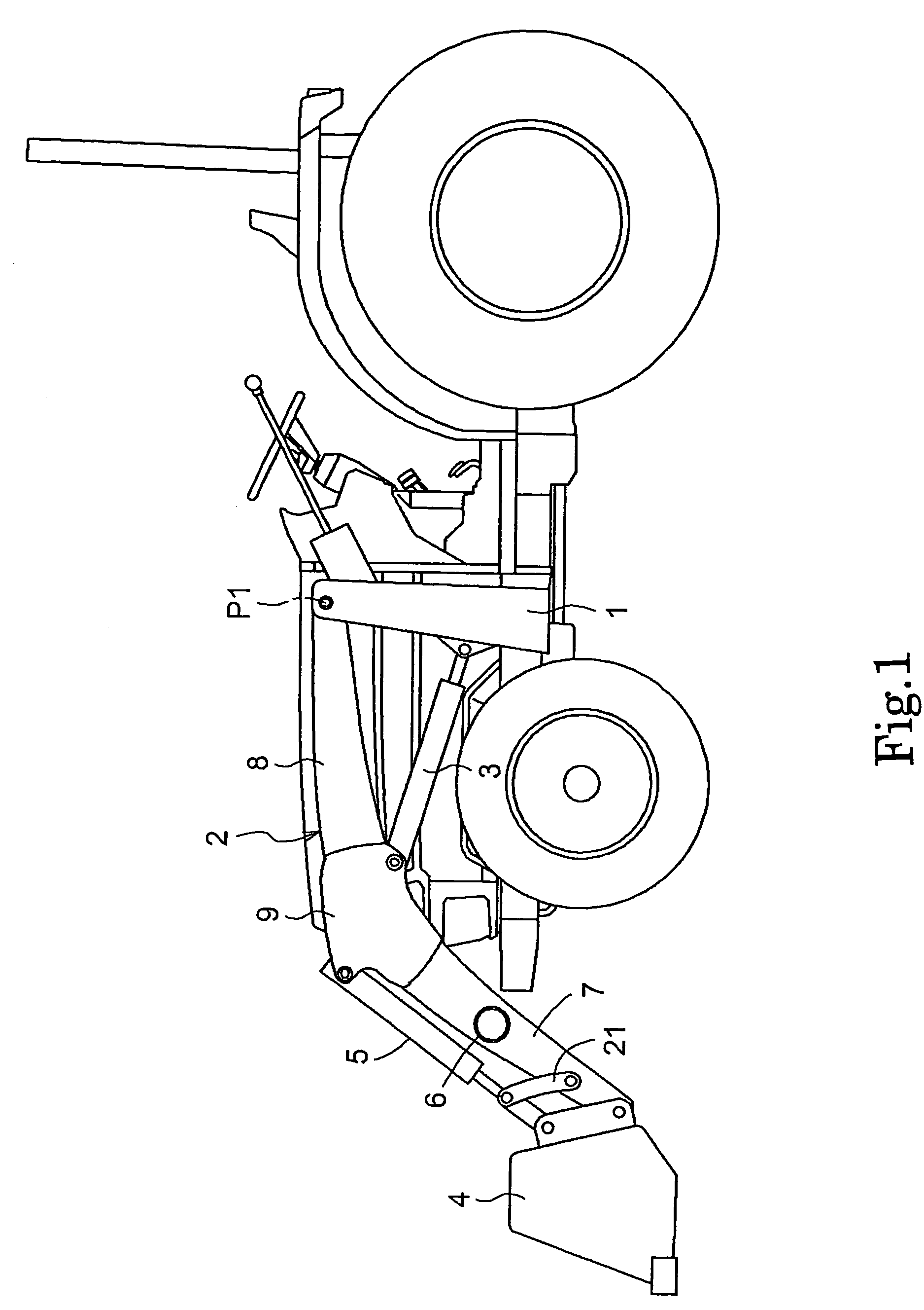
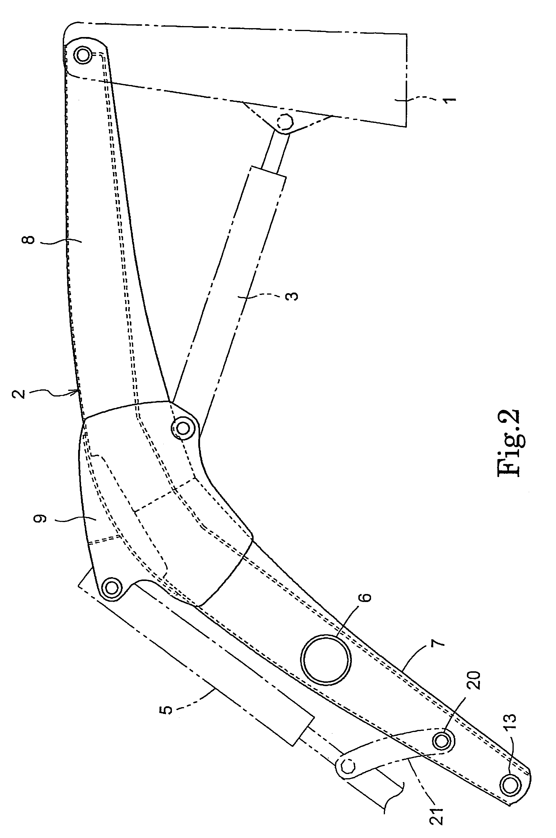
BACKGROUND OF THE INVENTION[0001]The present invention relates to a press-working method in which a blank is cut out from a sheet material and the cut-out blank is press-worked.[0002]An agricultural tractor such as that disclosed in Japanese Patent No. 2003-278176 (FIGS. 1, 3, 8, 11) has a front loader, which is an example of a excavating equipment, connected to a front part of a machine body, wherein the front loader comprises right and left booms, a bucket, and the like. The booms comprise a front structural member, a rear structural member, and an intermediate structural member. The front and intermediate structural members and the rear and intermediate structural members are respectively connected by welding.[0003]The front and rear structural members are bent to have a U-shaped cross section, and a flat-plate lower wall is connected to a side wall (wall) by welding. In this case, as described in FIGS. 15-16, the front and rear structural members of the booms are blanks (31) hav...

Claims


Application Information

Patent Timeline
Patent Type & Authority Patents(United States)
IPC IPC(8): B21D28/00B21D31/02
CPCB21D5/01B21D53/84Y10T29/4998Y10T29/49789
Inventor NISHI, TOSHIOINOUE, HIROFUMI
Owner KUBOTA CORP
Learn More