
Method and system for routing

a routing system and routing method technology, applied in the field of routing methods and systems, can solve the problems of increasing the total wirelength, the routing direction is not typically explored diagonally, and the lack of diagonal exploration increases the total length, so as to facilitate route modeling and congestion measurement, and reduce the number of nodes

Inactive Publication Date: 2009-11-24
CADENCE DESIGN SYST INC
View PDF4 Cites 11 Cited by
  • Summary
  • Abstract
  • Description
  • Claims
  • Application Information

AI Technical Summary

Benefits of technology

The patent describes methods and systems for modeling routes and measuring congestion using Gcells. These techniques can help improve route planning and congestion analysis, particularly for diagonal routing paths. The invention reduces the number of nodes used for modeling and congestion measurement, making it more efficient. Overall, the patent provides a solution for better understanding and managing traffic congestion.

Problems solved by technology

While some commercial global routers today might allow an occasional diagonal jog, these routers do not typically explore diagonal routing directions consistently when they are specifying the routing geometries of the interconnect lines.
This lack of diagonal exploration increases the total wirelength (i.e., total length of interconnect lines) needed to connect the nets in the layout.

Method used


Image

  • Method and system for routing
  • Method and system for routing
  • Method and system for routing

Examples


Embodiment Construction

[0027]In the following description, numerous details are set forth for purpose of explanation. However, one of ordinary skill in the art will realize that the invention may be practiced without the use of these specific details. In other instances, well-known structures and devices are shown in block diagram form in order not to obscure the description of the invention with unnecessary detail.

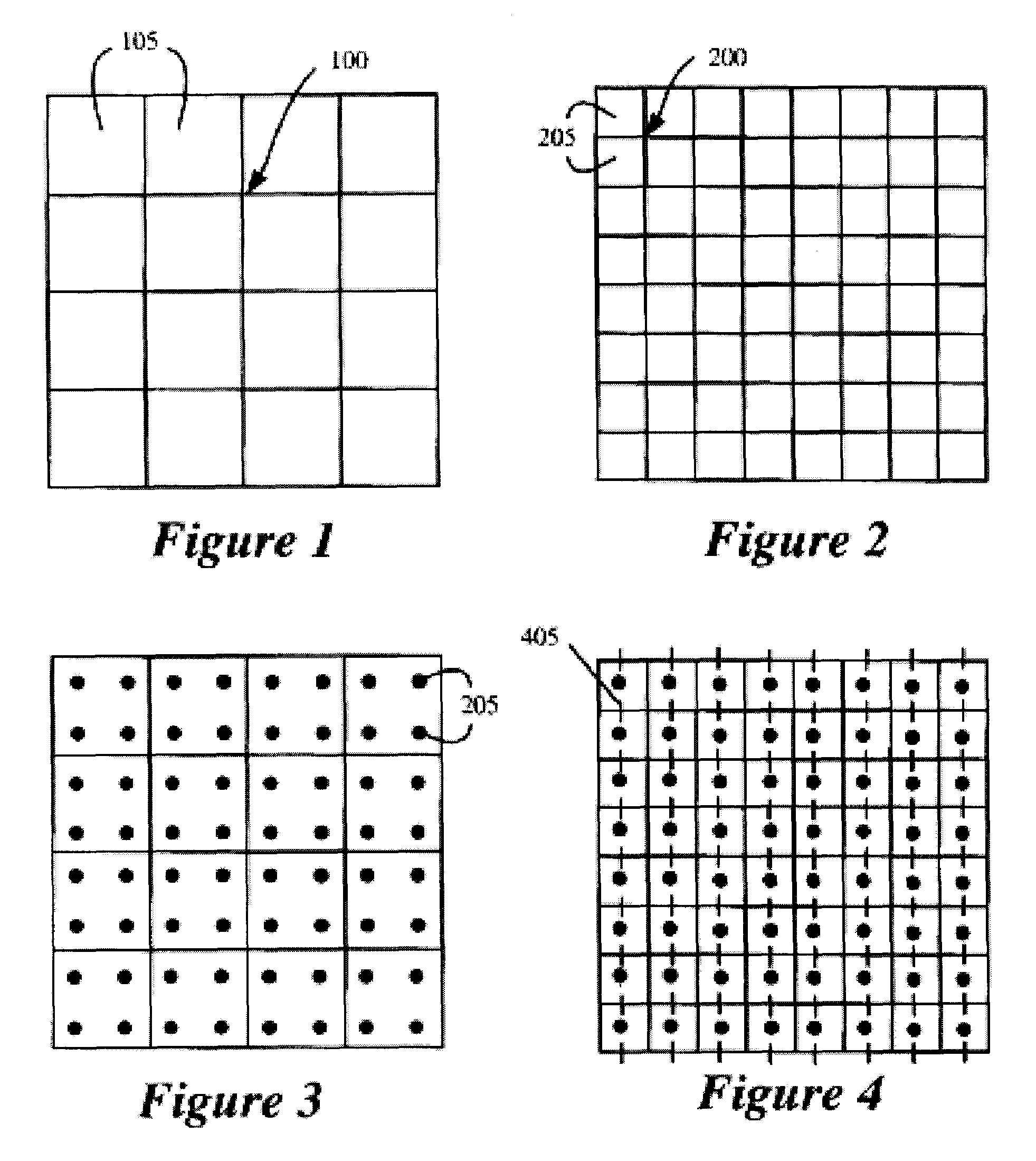
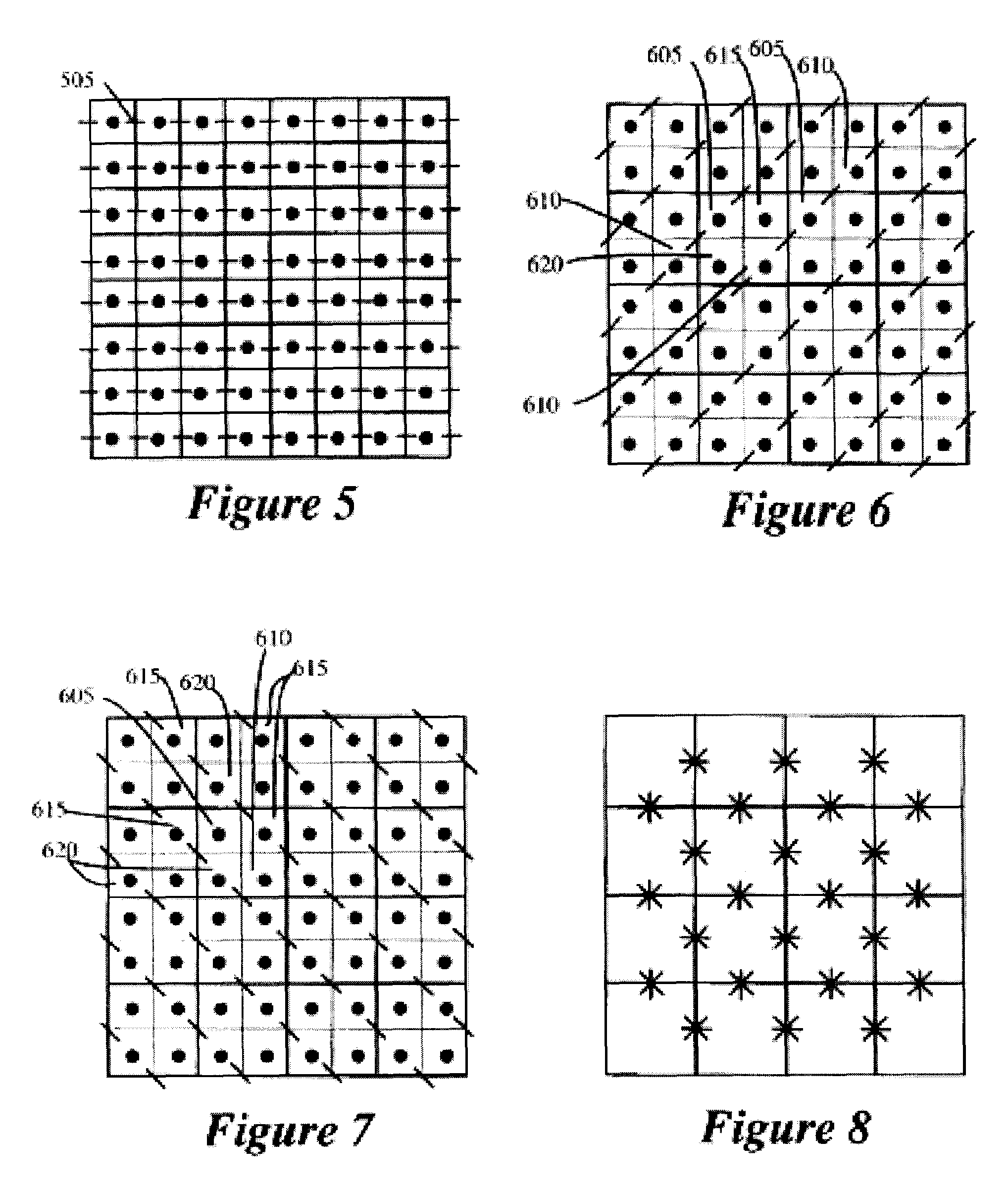
[0028]Some embodiments of the invention are methods and systems for implementing techniques for routing, modeling routes, and measuring congestion. In some embodiments, Gcells are implemented with fewer nodes to facilitate route modeling and congestion measurement.

[0029]Several embodiments of the invention provide a router that routes a set of nets in a region of an integrated circuit (“IC”) layout. Each routed net includes a set of routable elements in the IC-layout region. The routable elements are pins in the embodiments described below, although they might be other elements in other embodim...


PUM


Abstract

Disclosed is a method, system, and computer program product for routing, modeling routes, and measuring congestion. In some embodiments, Gcells are implemented with reduced number of nodes to facilitate route modeling and congestion measurement. Some embodiments are particularly suitable for direct congestion and routing analysis of diagonal routing paths. In this way, congestion analysis can be directly performed along diagonal boundaries for diagonal routes, without requiring association with Gcell boundaries on Manhattan routing layers.

Description

CROSS-REFERENCE TO RELATED APPLICATIONS[0001]The present application claims the benefit of U.S. Provisional Application Ser. No. 60 / 877,942, filed on Dec. 29, 2006. The present application is also a continuation-in-part of U.S. application Ser. No. 10 / 335,180, filed on Dec. 31, 2002, which claims priority to U.S. Provisional Application Ser. No. 60 / 427,131, filed on Nov. 18, 2002. All of the above-referenced applications are hereby incorporated by reference in their entirety.BACKGROUND AND SUMMARY[0002]An integrated circuit (“IC”) is a device (e.g., a semiconductor device) that includes many electronic components, such as transistors, resistors, diodes, etc. These components are often interconnected to form multiple circuit components, such as gates, cells, memory units, arithmetic units, controllers, decoders, etc. An IC includes multiple layers of wiring that interconnect its electronic and circuit components. Traditionally, IC's use preferred direction (“PD”) wiring models, which...

Claims


Application Information

Patent Timeline
Patent Type & Authority Patents(United States)
IPC IPC(8): G06F17/50
CPCG06F17/5077G06F30/394
Inventor FRANKLE, JONATHANGILCHRIST, III, JOHN H.MALHOTRA, ANISH
Owner CADENCE DESIGN SYST INC
Learn More