Thermal conducting medium protector

a technology of thermal conducting medium and protector, which is applied in the direction of snap fasteners, semiconductor/solid-state device details, lighting and heating apparatus, etc., can solve the problems of easy damage to the heat dissipation device or the thermal conducting medium, the conventional thermal conducting medium protector fixed via a bonder is not secure, and the operational elements generate a considerable amount of heat. , to achieve the effect of easy disassembly

Inactive Publication Date: 2009-11-24
COMPAL ELECTRONICS INC
View PDF9 Cites 14 Cited by
  • Summary
  • Abstract
  • Description
  • Claims
  • Application Information

AI Technical Summary

Benefits of technology

[0011]The present invention is further directed to a thermal conducting medium protector, which is firmly held onto the carrier via a mechanical buckling structure, and is easy to be detached from the carrier.
[0019]The thermal conducting medium protector of the present invention adopts a mechanical buckling structure, so the thermal conducting medium protector is not only firmly assembled to the carrier, but also can be easily detached. Furthermore, when assembling the thermal conducting medium protector, the positioning portion can be inserted into the socket opening, so as to prevent the thermal conducting medium protector from sliding too much with respect to the socket. In addition, the thermal conducting medium protector is covered on the socket after being assembled, thereby protecting plugholes in the socket from being blocked by foreign substances.

Problems solved by technology

During the operation of a computer, several of the operational elements generate a considerable amount of heats.
Accordingly, as known from the two cases disclosed above, the conventional thermal conducting medium protector fixed via a bonder is not secure.
Moreover, when the conventional thermal conducting medium protector is removed from the heat dissipation device, it may easily damage the heat dissipation device or the thermal conducting medium.
For example, when the conventional thermal conducting medium protector is removed from the heat dissipation device, a portion of the bonder is remained on the heat dissipation device, thus affecting the heat dissipation effect of the heat dissipation device.
Moreover, if the thermal conducting medium protector falls off when being detached due to carelessness, the integrity of the thermal conducting medium may be easily affected.

Method used


Image

  • Thermal conducting medium protector
  • Thermal conducting medium protector
  • Thermal conducting medium protector

Examples


Embodiment Construction

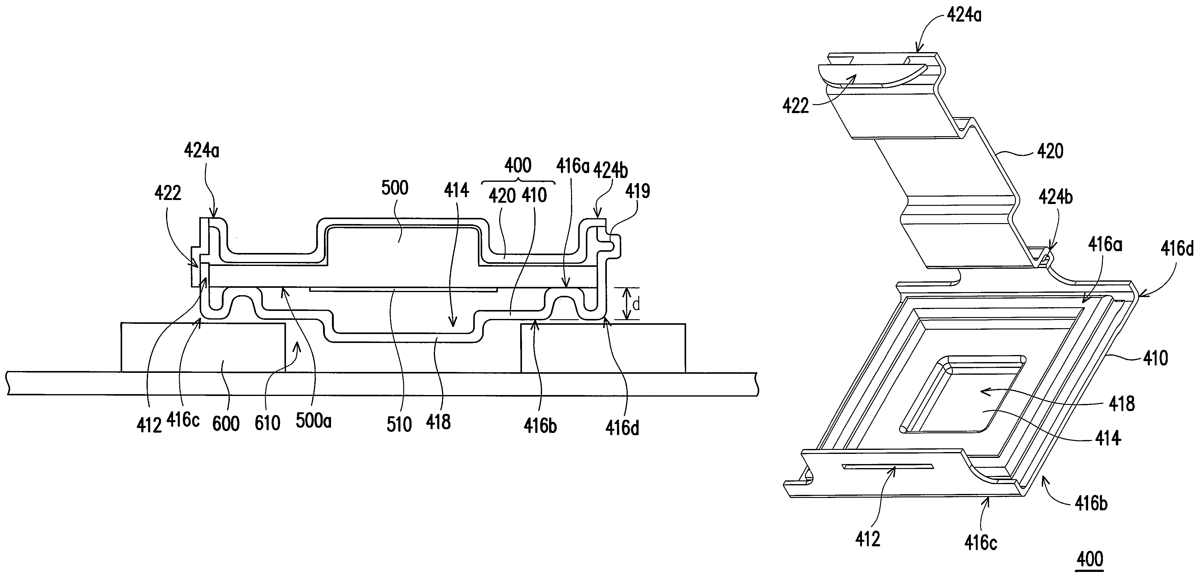
[0026]FIG. 3A illustrates a thermal conducting medium protector assembled to a carrier according to an embodiment of the present invention, and FIG. 3B is a perspective view of a thermal conducting medium protector in FIG. 3A before the first buckling portion is buckled with the second buckling portion. Referring to FIG. 3A and FIG. 3B, a thermal conducting medium protector 400 is applicable for being assembled to a carrier 500, so as to protect a thermal conducting medium 510 disposed on a surface 500a of the carrier 500.

[0027]In this embodiment, the carrier 500 is, for example, a heat dissipation device, a heat block, a heat pipe, or another means with a thermal conducting function, and the thermal conducting medium 510 is, for example, thermal grease, thermal conducting tape, or another thermal conducting medium suitable for conducting heats. Moreover, the thermal conducting medium protector 400 is suitable for cladding the carrier 500 and the thermal conducting medium 510, so as...


PUM


Abstract

A thermal conducting medium protector is applicable for being assembled to a carrier, so as to protect a thermal conducting medium disposed on the carrier. The thermal conducting medium protector includes a shell and a cover plate. The shell has a first buckling portion on one side of the shell, and an opening. When the carrier is placed on a side surface of the shell, the thermal conducting medium is located in the opening. The cover plate has a second buckling portion, a first side, on which the second buckling portion is located, and a second side opposite to the first side and pivoted to the shell. When the cover plate rotates along the second side and then span across the carrier placed on the side surface of the shell, the buckling portions are buckled with each other to hold the carrier between the shell and the cover plate.

Description

CROSS-REFERENCE TO RELATED APPLICATION[0001]This application claims the priority benefit of Taiwan application serial no. 95127925, filed Jul. 31, 2006. All disclosure of the Taiwan application is incorporated herein by reference.BACKGROUND OF THE INVENTION[0002]1. Field of the Invention[0003]The present invention relates to a protector. More particularly, the present invention relates to a thermal conducting medium protector.[0004]2. Description of Related Art[0005]During the operation of a computer, several of the operational elements generate a considerable amount of heats. As the processing speed of the computer increases, the central processing unit (CPU) generates even greater heats. The heat generated by the CPU is usually dissipated by attaching a heat dissipation device with fins to the bare chip of the CPU, such that the heat is transferred from the chip to the heat dissipation device, and then dissipated into the open air by the fins.[0006]To make the heat dissipation dev...

Claims


Application Information

Patent Timeline
Patent Type & Authority Patents(United States)
IPC IPC(8): H05K7/20F28F7/00H01L23/34
CPCH01L21/4882H01L23/40H01L23/3737H01L2924/0002Y10T24/44556Y10T24/44034Y10T24/44026H01L2924/00
Inventor TIEN, CHI-WEIWU, CHANG-YUANTU, CHING-YA
Owner COMPAL ELECTRONICS INC
Why Eureka
Try Eureka