
Portable information terminal

a telephone terminal and portability technology, applied in the direction of electrical apparatus construction details, coupling device connections, electrical apparatus casings/cabinets/drawers, etc., can solve the problems of difficult operation of keys in positions close to the upper casing b>1/b> on the operating unit, and not solve basic problems, etc., to achieve the effect of convenient us

Inactive Publication Date: 2009-11-24
SNAPTRACK
View PDF16 Cites 6 Cited by
  • Summary
  • Abstract
  • Description
  • Claims
  • Application Information

AI Technical Summary

Benefits of technology

The design enables substantial expansion of the operating and display faces in a usable state without increasing the portable state size, providing easier operation and a compact form, with the ability to stop the turning mechanism in both states, allowing for a linearly symmetrical design and minimizing the terminal's thickness and width.

Problems solved by technology

However, this does not solve basic problems such as the problem wherein the keys in positions close to the upper casing 1 on the operating unit 5 are difficult to operate.

Method used


Image

  • Portable information terminal
  • Portable information terminal
  • Portable information terminal

Examples


first embodiment

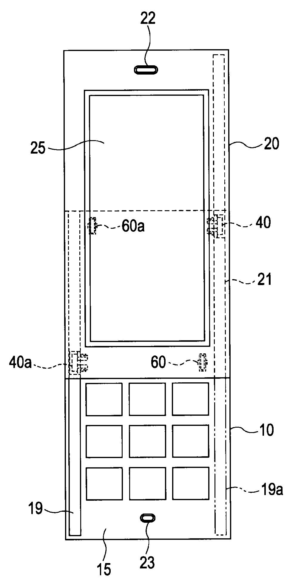
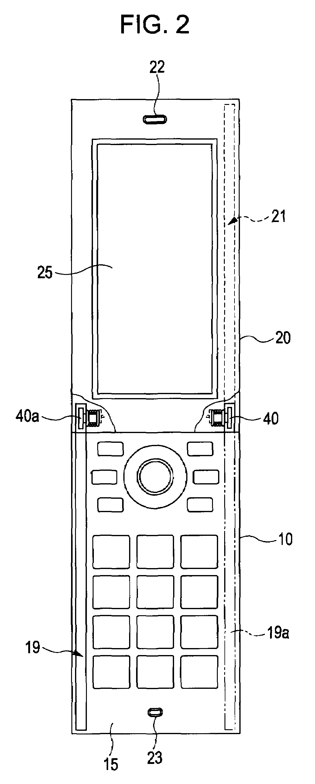
[0045]FIGS. 2 through 4C illustrate a portable telephone terminal according to the

[0046]The first casing 10 has a numeric keypad operating face 15, and the second casing 20 has operating keys such as a liquid crystal output face 15, speaker 22, microphone 23, and arrow keys 24. The sizes of the first casing 10 and second casing 20 in the planar direction are rectangles of roughly the same size. The lengthwise direction of the rectangles is the sliding direction.

[0047]The operating face 15 of the first casing 10 has a sliding groove 19 along both edges on the lengthwise side, as shown in FIG. 3C. The sliding groove 19 is fixed so that the sliding supporting member 40 which forms an oval-shaped plate is slidable. The second casing 20 is fixed so as to be capable of turning on the opposite side of the sliding groove 19 with the sliding supporting member 40.

[0048]Also, a second casing supporting roller 60 for smoothly sliding while in contact with the second casing 20 is axially support...

second embodiment

[0068]FIG. 10A illustrates a That is to say, the portable information terminal employs a keyboard casing 10a having a full keyboard for the first casing on the operating face, and employs a display screen casing 20a with an almost full-face output screen for the second casing. This is an embodiment primarily readily usable for a PDA, but can be used for a portable telephone terminal also, by creatively employing a portion of the output screen as a patch panel or employing operating buttons on the side face of the casing.

third embodiment

[0069]FIG. 10B illustrates a That is to say, both the first casing and second casing have a liquid crystal display screen, wherein the first casing is a touch panel casing 10b of a patch panel type combined with an input device as necessary, and the second casing also is a touch panel casing 20b of a patch panel type combined with an input device as necessary. This is an embodiment primarily readily usable for gaming device, but can be used for a portable telephone terminal or PDA also, by creatively employing a portion of the output screen as a patch panel or employing operating buttons on the side face of the casing.

(Casing Dimension Variation)


PUM


Abstract

A portable information terminal has a first casing, a second casing, a sliding mechanism to maintain a portable state wherein the first casing and second casing are overlapped, and a turning mechanism to modify the from the portable state, via a sliding state wherein the first casing and second casing mutually slide, into a usable state. The sliding mechanism engages with sliding grooves provided on each of the first casing and second casing, and provides axially supported sliding members. The turning mechanism has a member to limit the turning angle of the sliding members, whereby a state can be maintained when usable of the first casing and second casing forming a single face. Thus, a sliding-type portable information terminal is provided with an expanded operating face and output face by doing away with any overlapped portion.

Description

CROSS REFERENCES TO RELATED APPLICATIONS[0001]The present invention contains subject matter related to Japanese Patent Application JP 2007-224786 filed in the Japanese Patent Office on Aug. 30, 2007, the entire contents of which are incorporated herein by reference.BACKGROUND OF THE INVENTION[0002]1. Field of the Invention[0003]The present invention relates to a portable telephone terminal, and specifically relates to a portable information terminal such as a portable telephone terminal, portable gaming device, or palm-size personal computer which can be altered between a portable state and usable state.[0004]2. Description of the Related Art[0005]Portable information terminals which are represented by a portable telephone terminal or the like are being developed in various forms so as to be more compact in a portable state than in a usable state. Representative forms thereof include a so-called “shell-form” (flip-phone) which employs a configuration which opens and closes similar t...

Claims


Application Information

Patent Timeline
Patent Type & Authority Patents(United States)
IPC IPC(8): H05K7/14H04M1/00
CPCH04M1/0237H04M1/0216
Inventor MIYAOKA, HIDEKAZU
Owner SNAPTRACK
Learn More