
Auger with tapered flighting

a technology of tapered flight and auger, which is applied in the field of machines for harvesting crops, can solve the problems of increasing the difficulty of subsequent harvesting operations, loss of harvesting productivity, and seed loss

Active Publication Date: 2009-11-24
BLUE LEAF I P INC
View PDF20 Cites 19 Cited by
  • Summary
  • Abstract
  • Description
  • Claims
  • Application Information

AI Technical Summary

Benefits of technology

[0006]Accordingly, it is an object of the present invention to provide a crop harvesting header which efficiently gathers severed crop from a cutterbar and conveys it to a discharge zone and there deposits the crop evenly to form a uniform crop mat for discharge to a windrow or for intake by a subsequent crop processing apparatus.
[0007]It is a further object of the present invention to provide a transversely arranged crop conveyance mechanism which conveys severed crop to a discharge zone without undue disturbance of a specialty, seed-bearing crop material which could result in seed loss.
[0010]It is a still further object of the present invention to provide a transversely arranged auger mechanism for conveying severed crop material toward a central discharge zone that does not result in clogging or entanglement of the severed crop material with the mechanism.
[0013]It is yet another object of the present invention to provide a crop conveying auger having standard interface connections with existing header designs thereby enabling efficient manufacturing of specialty headers.
[0014]It is a still further object of the present invention to provide a transversely arranged crop conveyance mechanism which conveys severed crop to a discharge zone without undue disturbance of the crop material that is durable in construction, inexpensive of manufacture, carefree of maintenance, easily assembled, and simple and effective to use.
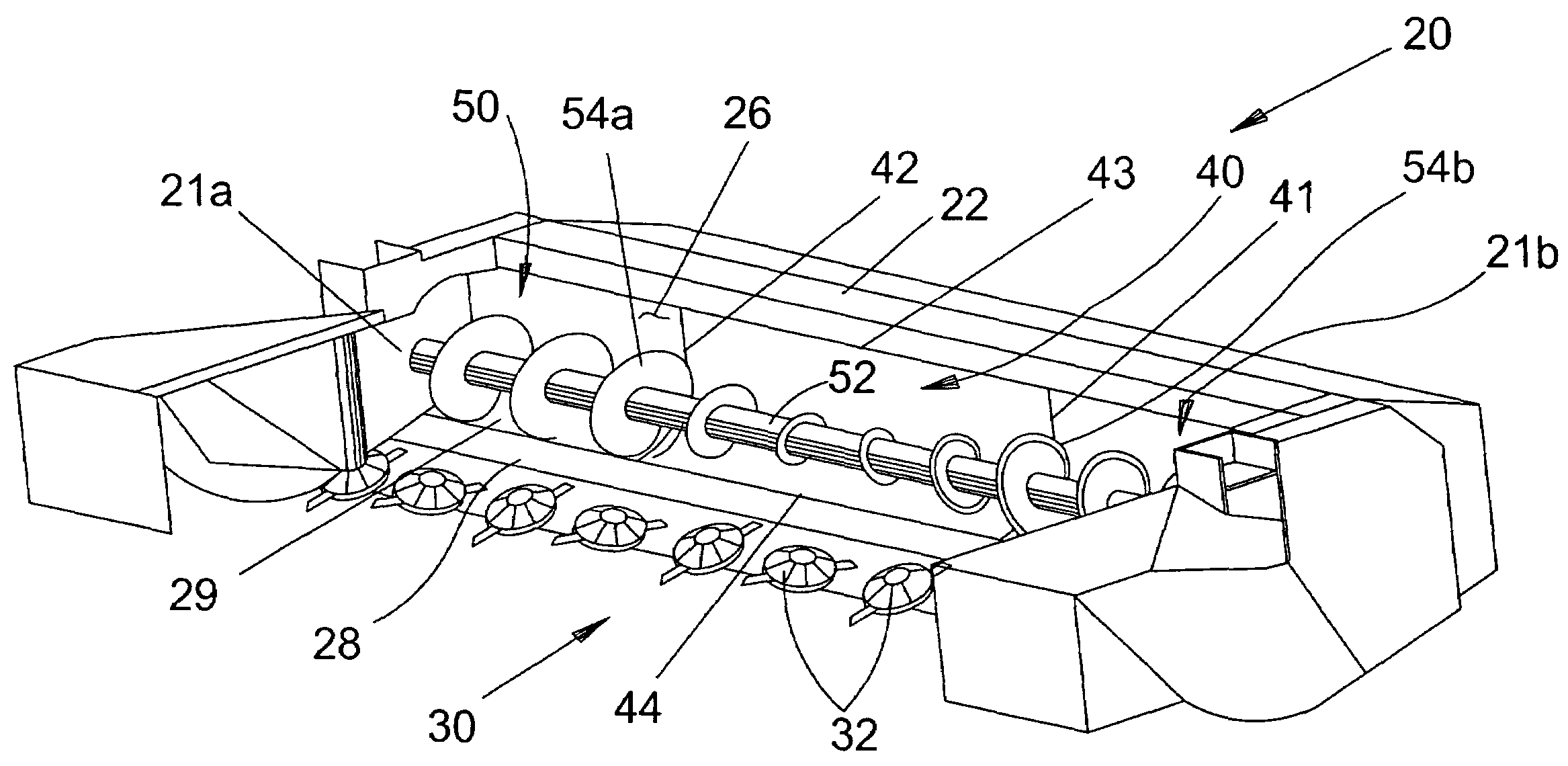
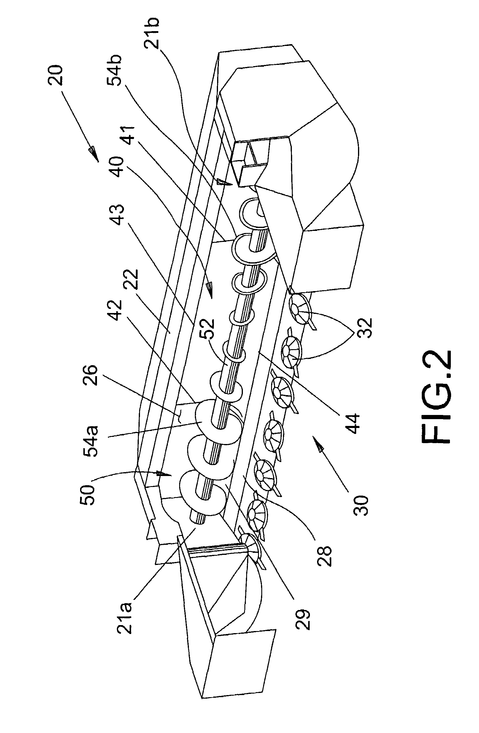
[0015]These and other objects are achieved according to the instant invention by providing a crop conveying apparatus for laterally urging crop from outboard ends of a cutting header on an agricultural harvester toward an interior discharge zone for formation of a windrow or for feed to a subsequent crop processing apparatus. Helical flighting extending radially from a transversely disposed, rotatable central core defines a first profile for the auger apparatus adjacent each outboard end of the header and extending inwardly to a position near, but not co-extensive with the width of a crop discharge zone in the header. Auger flighting in the central portion of the header co-extensive with the width of the discharge zone opening features a variable profile that tapers from the first profile to a minimum profile centrally located between the side edges of the discharge zone opening to provide optimal movement of severed crop material into the discharge opening, resist entanglement and clogging of the crop material, and minimize the loss of seed from the crop stem.

Problems solved by technology

Clogs result in lost harvesting productivity while an operator removes the entangled crop and also lost seed due to the increased disruption to the crop material when the entanglement begins.
In many conditions, the tendency of crops to clog results in clumping in the resultant windrow which increases the difficulty of subsequent harvesting operations, such as threshing by a combine.
Experience has shown that this same structure delivers unsatisfactory windrowing in the absence of the conditioning mechanism.
Replacing the paddle structures with flighting continuing to the center of the auger has also proven unsatisfactory as it causes large clogs of crop material to form in the center of the header resulting in uneven windrows.

Method used


Image

  • Auger with tapered flighting
  • Auger with tapered flighting
  • Auger with tapered flighting

Examples


Embodiment Construction

)

[0020]Many of the fastening, connection, processes and other means and components utilized in this invention are widely known and used in the field of the invention described, and their exact nature or type is not necessary for an understanding and use of the invention by a person skilled in the art, and they will not therefore be discussed in significant detail. Also, any reference herein to the terms “left” or “right” are used as a matter of mere convenience, and are determined by standing at the rear of the machine facing in its normal direction of travel. Likewise, “forward” and “rearward” are determined by the normal direction of travel. “Upward” and “downward” orientations are relative to the ground or operating surface as are any references to “horizontal” or “vertical” planes. Furthermore, the various components shown or described herein for any specific application of this invention can be varied or altered as anticipated by this invention and the practice of a specific ap...


PUM


Abstract

A crop conveying apparatus for laterally urging crop from outboard ends of a cutting header on an agricultural harvester toward an interior discharge zone for formation of a windrow or for feed to a subsequent crop processing apparatus. Helical flighting extending radially from a transversely disposed, rotatable central core defines a first profile for the auger apparatus adjacent each outboard end of the header and extending inwardly to a position near, but not co-extensive with the width of a crop discharge zone in the header. Auger flighting in the central portion of the header co-extensive with the width of the discharge zone opening features a variable profile that tapers from the first profile to a minimum profile centrally located between the side edges of the discharge zone opening to provide optimal movement of severed crop material into the discharge opening, resist entanglement and clogging of the crop material, and minimize the loss of seed from the crop stem.

Description

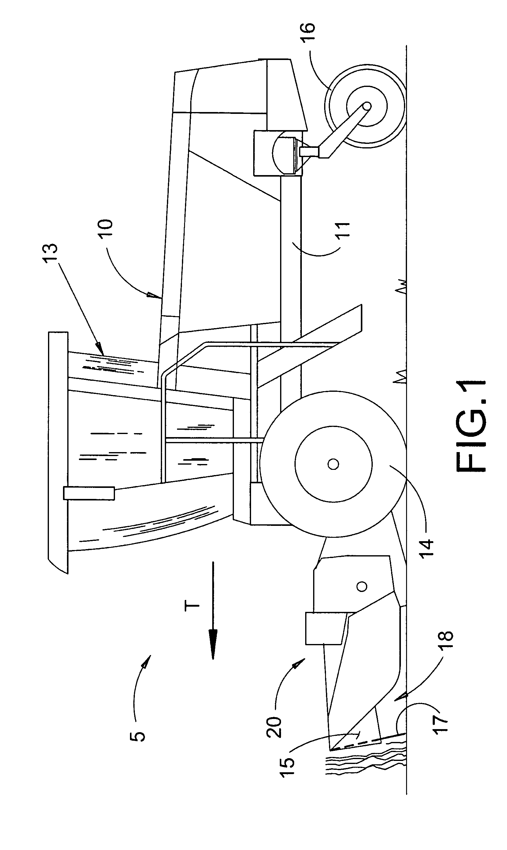
BACKGROUND OF THE INVENTION[0001]This invention relates generally to a machine for harvesting crops in a field and forming a windrow of cut crop, more particularly, to a specialized header for harvesting specialty crop with an apparatus for transversely conveying the crop material within the header without damaging the crop.[0002]In modern crop harvesting machines, it is desirable to optimize cutting headers for specific crops in order to maximize harvesting efficiency. Such optimized headers are typically based on existing headers with specific-purpose modifications incorporated to alter finite portions of the crop flow within the header to suit the specific crop. This approach helps control production costs of the equipment and extends the life cycle of a basic header design.[0003]One specific application involves harvesting of grasses, seed or other specialty crops having seeds on a stem which must be cut and dried in a windrow a desired amount before undertaking operations to se...

Claims


Application Information

Patent Timeline
Patent Type & Authority Patents(United States)
IPC IPC(8): A01D34/00A01D43/00
CPCA01D61/004B65G65/22
Inventor BLAKESLEE, EDWARD A.THAXTON, WAYNE D.
Owner BLUE LEAF I P INC
Learn More