
Wheel bearing arrangement comprising an encoder and a sensor

Inactive Publication Date: 2009-11-17
SCHAEFFLER TECH AG & CO KG
View PDF8 Cites 7 Cited by
  • Summary
  • Abstract
  • Description
  • Claims
  • Application Information

AI Technical Summary

Benefits of technology

[0008]It is therefore the object of the invention to provide a wheel bearing arrangeme

Problems solved by technology

When mounting the sensor and when exchanging the sensor during the course of repair work, there is the risk of dirt passing into the interior of the seal and therefore into the region of rolling contact between the rolling bodies and the rolling bodies

Method used


Image

  • Wheel bearing arrangement comprising an encoder and a sensor
  • Wheel bearing arrangement comprising an encoder and a sensor
  • Wheel bearing arrangement comprising an encoder and a sensor

Examples


Example

DESCRIPTION OF THE DRAWINGS

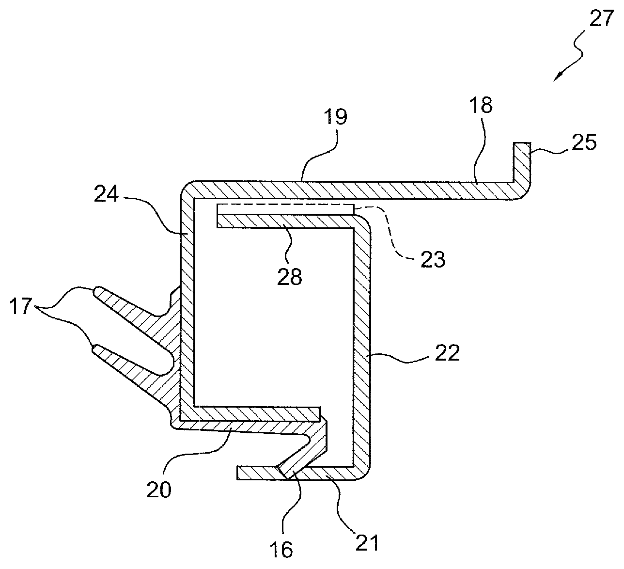
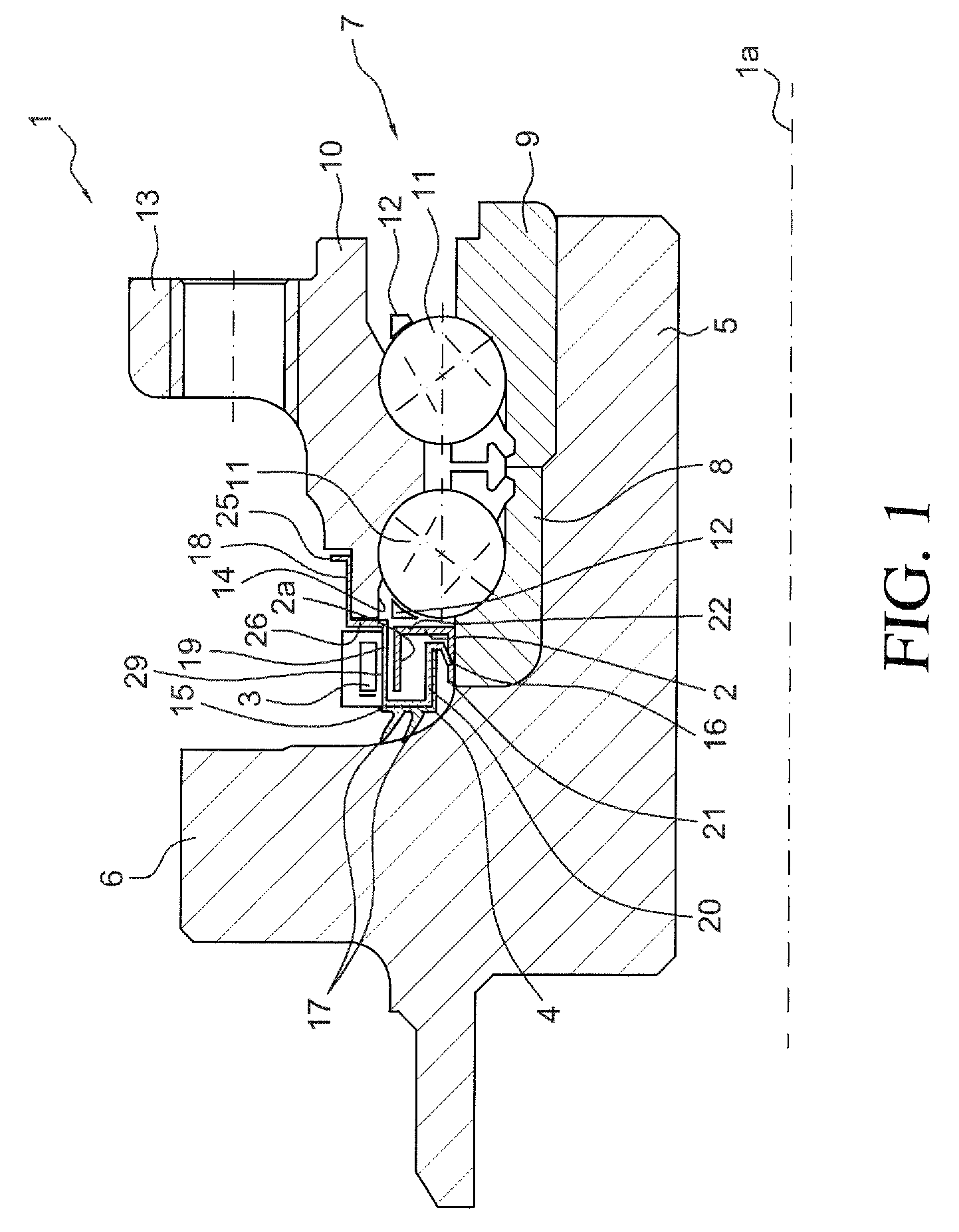
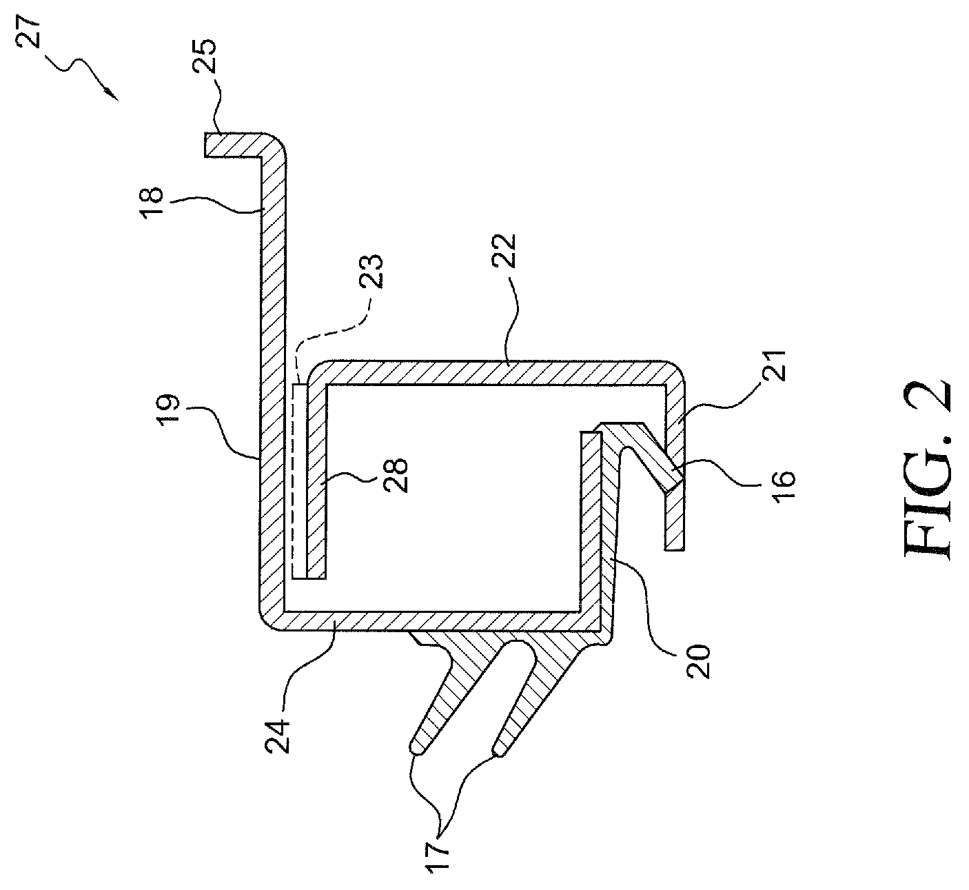
[0034]FIG. 1 shows a wheel bearing arrangement 1 in a section illustration along the rotational axis 1a. The wheel bearing arrangement 1 has at least one encoder 2, at least one sensor 3, a seal 4 which is arranged concentrically with respect to the rotational axis 1a, and a hub 5 which is mounted in the wheel bearing arrangement 1 so as to be rotationally moveable. The hub 5 has a radial flange 6 which is in this case formed in one piece with the hub 5 and is aligned radially away from the rotational axis 1a. The radial flange 6 is provided for fastening a vehicle wheel (not illustrated) at the left-hand side in the figure. The hub 5 and therefore the vehicle wheel are mounted so as to be rotatable about the rotational axis 1a by means of a wheel bearing 7. The wheel bearing 7 is in this case formed by two inner rings 8 and 9, an outer ring 10 and rolling bodies 11 in cages 12. The outer ring 10 is embodied as a wheel carrier and has, for this purpose, a ...


PUM


Abstract

The invention relates to a wheel bearing arrangement, comprising at least one encoder, at least one sensor, a seal arranged concentrically to the rotational axis and a hub mounted to rotate in the wheel bearing arrangement, whereby a radial flange on the hub, faces radially away from the rotation axis and the seal seals at least one radial annular gap around the hub on the side of the radial flange. The seal comprises at least one cover ring, made from a non-ferromagnetic material and at least one elastic first sealing lip, the first sealing lip is fixed to the cover ring and makes sealing contact with the encoder and at least one signal-active part of the encoder is arranged on the inside of the seal and rotates about the rotational axis with the hub.

Description

FIELD OF THE INVENTION[0001]The invention relates to a wheel bearing arrangement having at least one encoder, having at least one sensor, having a seal which is arranged concentrically with respect to the rotational axis, and having a hub which is mounted in the wheel bearing arrangement so as to be rotationally moveable, with:[0002]a radial flange of the hub being aligned radially away from the rotational axis,[0003]the seal sealing off at least one radial annular gap around the hub at the side of the radial flange,[0004]the seal having at least one covering ring, which is made from a non-ferromagnetic material, and at least one elastic first sealing lip,[0005]the first sealing lip being fixed to the covering ring and bearing sealingly against the encoder,[0006]the encoder being arranged at the inside of the seal and being rotationally moveable about the rotational axis with the hub.BACKGROUND OF THE INVENTION[0007]A wheel bearing arrangement of said type is described in U.S. Pat. ...

Claims


Application Information

Patent Timeline
IPC IPC(8): F16C32/00F16C19/18F16C33/78F16C41/00G01P3/44
CPCF16C19/185F16C33/7886G01P3/443F16C41/007F16C2326/02
Inventor HAEPP, ALEXANDERWALTER, WILHELM
Owner SCHAEFFLER TECH AG & CO KG
Learn More