
Method and apparatus for accessing a memory

a technology for accessing memory and methods, applied in the direction of memory address formation, micro-instruction address formation, etc., can solve the problems of excessive delays and inefficiencies in the operation of the computer system, time-consuming and expensive registration process,

Inactive Publication Date: 2009-11-10
HEWLETT-PACKARD ENTERPRISE DEV LP
View PDF44 Cites 92 Cited by
  • Summary
  • Abstract
  • Description
  • Claims
  • Application Information

AI Technical Summary

Benefits of technology

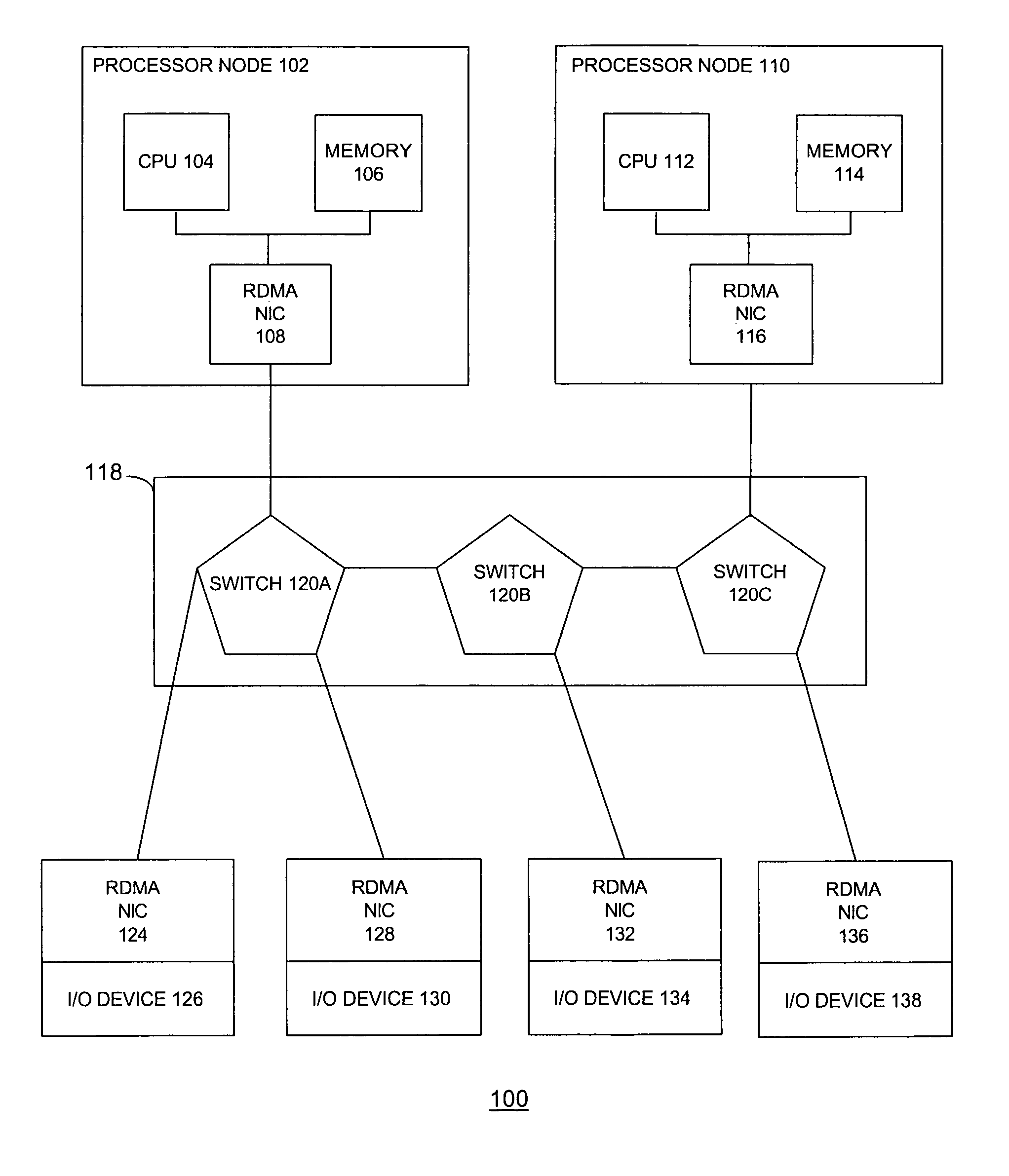
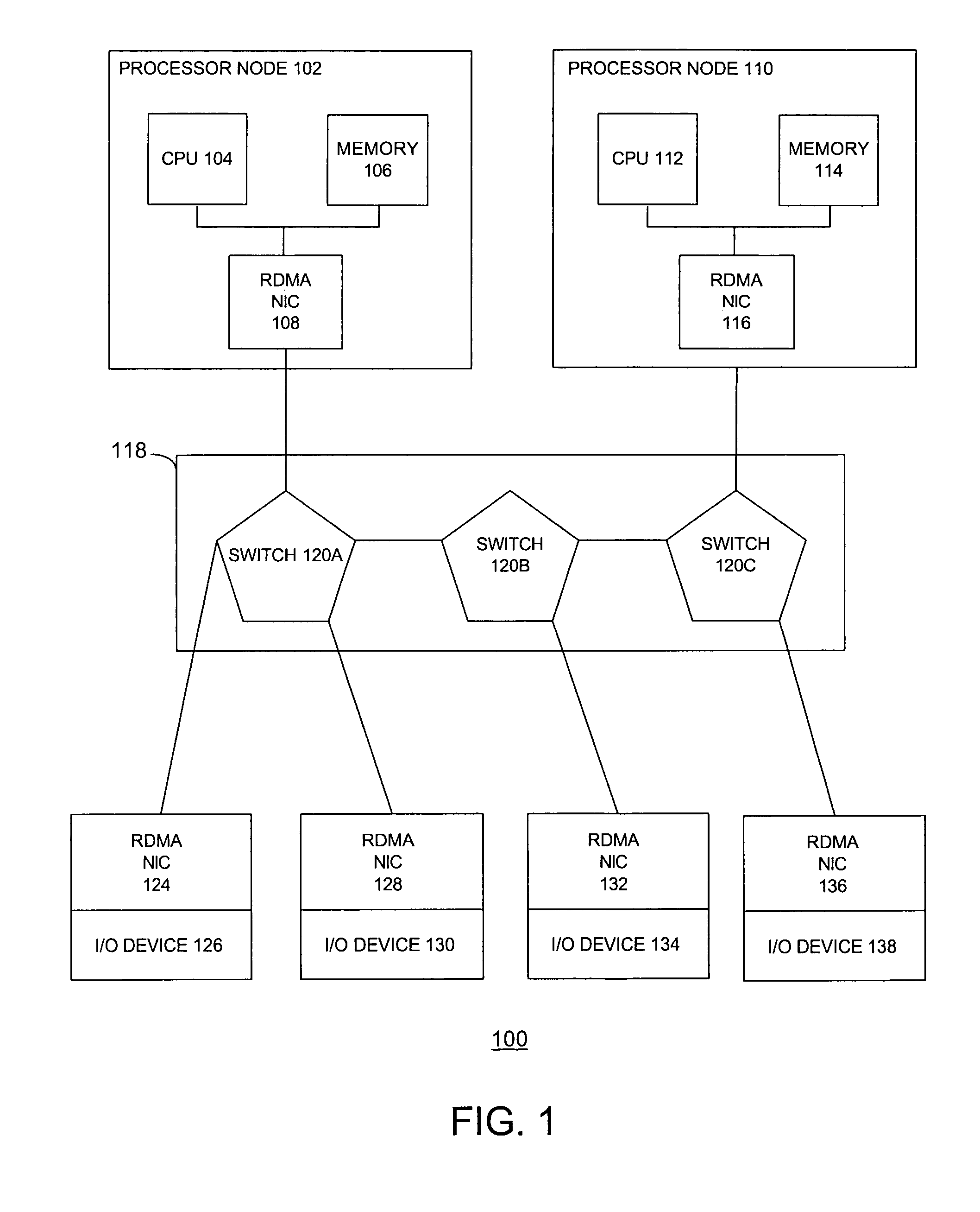
[0012]RDMA may refer to the ability of one computer to directly place information in the memory space of another computer, while minimizing demands on the central processing unit (“CPU”) and memory bus. In an RDMA system, an RDMA layer may interoperate over any physical layer in a Local Area Network (“LAN”), Server Area Network (“SAN”), Metropolitan Area Network (“MAN”), or Wide Area Network (“WAN”).

Problems solved by technology

The registration process is time consuming and expensive in terms of computing resources.
As such, for each command sent from the upper layer protocol, the extensive registration process may result in excessive delays and inefficiencies in the operation of the computer system.

Method used


Image

  • Method and apparatus for accessing a memory
  • Method and apparatus for accessing a memory
  • Method and apparatus for accessing a memory

Examples


Embodiment Construction

[0010]One or more specific embodiments of the present invention will be described below. In an effort to provide a concise description of these embodiments, not all features of an actual implementation are described in the specification. It should be appreciated that in the development of any such actual implementation, as in any engineering or design project, numerous implementation-specific decisions may be made to achieve the developers' specific goals, such as compliance with system-related and business-related constraints, which may vary from one implementation to another. Moreover, it should be appreciated that such a development effort might be complex and time consuming, but would nevertheless be a routine undertaking of design, fabrication, and manufacture for those of ordinary skill having the benefit of this disclosure.

[0011]The Remote Direct Memory Access (“RDMA”) Consortium, which includes the assignee of the present invention, is developing specifications to improve ab...


PUM


Abstract

The disclosed embodiments relate to an optimized memory registration mechanism that may comprise an upper layer protocol that associates I / O buffers with memory regions and that manages steering tags. The memory regions may be associated with a translation page table. The upper layer protocol may allocate one of the steering tags associated with at least one of the memory regions for a memory operation.

Description

BACKGROUND OF THE RELATED ART[0001]This section is intended to introduce the reader to various aspects of art, which may be related to various aspects of the present invention that are described and / or claimed below. This discussion is believed to be helpful in providing the reader with background information to facilitate a better understanding of the various aspects of the present invention. Accordingly, it should be understood that these statements are to be read in this light, and not as admissions of prior art.[0002]In the field of computer systems, it may be desirable for information to be transferred from a system memory associated with one computer system to a system memory associated with another computer system. The information may be transmitted by upper layer protocols (“ULP”), which may be referred to as consumers, through a network that connects the computer systems together. Many protocols or strategies for transferring data between the memories of computer systems em...

Claims


Application Information

Patent Timeline
Patent Type & Authority Patents(United States)
IPC IPC(8): G06F12/00G06F3/00G06F12/10G06F13/40
CPCG06F12/1081H04L67/00G06F13/4009
Inventor CHADALAPAKA, MALLIKARJUNBARRON, DWIGHT L.CULLEY, PAUL R.HILLAND, JEFFREY R.WENDT, JAMES G.
Owner HEWLETT-PACKARD ENTERPRISE DEV LP
Learn More