
Apparatus and method for determining GPS tracking loop parameter based on SNR estimation

a tracking loop and parameter technology, applied in the field of baseband signal processing in spread spectrum communication, can solve the problems of unlock status, inability to follow the gps signal in real time, and inability to change the unchangeable parameters

Active Publication Date: 2009-11-03
O2 MICRO INT LTD
View PDF7 Cites 18 Cited by
  • Summary
  • Abstract
  • Description
  • Claims
  • Application Information

AI Technical Summary

Benefits of technology

"The patent text describes methods and apparatus for estimating the signal-to-noise ratio of a spread spectrum signal with an in-phase component and a quadrature component. The methods involve determining correlation results between the signal and pseudorandom codes, and averaging the results to obtain the signal power and average noise power values. The peak value of the signal power is detected, and the average noise power is determined. The signal-to-noise ratio is then calculated based on the signal power and average noise power values. The technical effect of this patent is to provide a reliable and accurate measure of the signal-to-noise ratio of a spread spectrum signal, which can be used in various applications such as tracking and signal processing."

Problems solved by technology

However, the disadvantage of the unchangeable parameters becomes apparent when the signal strength of the received GPS signal changes.
For instance, when the SNR is high, if the integration time and the bandwidth of the tracking loops are not well-chosen and remain constant, the tracking loop will lead to an unlock status and will not be able to follow the GPS signal in real time.
When the SNR is low, the tracking loop will also not be able to follow the weak signal due to an unfavorable wide bandwidth of the tracking loop and a relatively short integration time period that might lead to a failure in peak value detection.

Method used


Image

  • Apparatus and method for determining GPS tracking loop parameter based on SNR estimation
  • Apparatus and method for determining GPS tracking loop parameter based on SNR estimation
  • Apparatus and method for determining GPS tracking loop parameter based on SNR estimation

Examples


Embodiment Construction

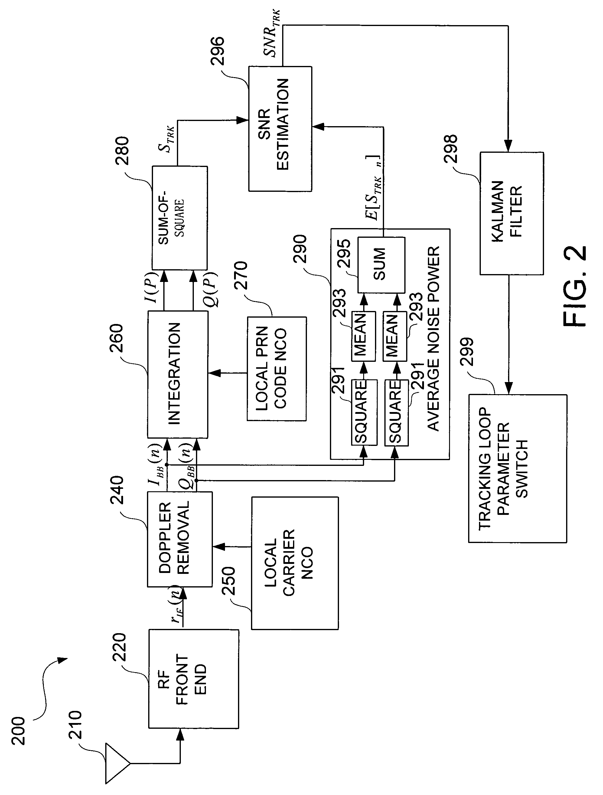
[0021]Usually, the parameters of the tracking module (bandwidth of the tracking loop and integration time) need to be initialized after the acquisition stage. These two parameters can be set accordingly by estimating the SNR of the received signal after acquisition is performed and before the tracking process started. Additionally, the parameters should be adjustable in real time during the tracking process based on the variation of the signal quality during the tracking process. Therefore, it is necessary to provide a real-time estimation of the SNR of the received signal during the tracking process to dynamically adjust the parameters. Consequently, there is provided two SNR estimation methods corresponding to the above two cases. One method is SNR estimation after the acquisition stage and before the tracking stage, where the parameters for the tracking loop can be initialized by using this method. The other method is another real-time SNR estimation during the tracking stage, wh...


PUM


Abstract

A method for estimating signal quality of a spread spectrum signal is provided. The method includes squaring a plurality of in-phase correlation results and a plurality of quadrature correlation results, summing each squared in-phase correlation result and the corresponding correlation result to obtain a plurality of sum-of-square values, detecting a peak value among the plurality of sum-of-square results, calculating an average of non-peak values among the plurality of sum-of-square results. The peak value is regarded as a signal power value, while the averaged non-peak values are regarded as an average noise power value. A signal-to-noise ratio is then calculated based on the signal power value and the average noise power value. A method for determining the parameters for the tracking loop is also provided. The method includes estimating the signal-to-noise ratio of the spread spectrum signal, and determining the tracking loop parameters based on the signal-to-noise ratio.

Description

FIELD OF THE INVENTION[0001]The invention relates to baseband signal processing in spread spectrum communication, more particular, to the determination of tracking loop parameters based on signal quality estimation.BACKGROUND OF THE INVENTION[0002]Spread spectrum communication is advantageous in communication applications requiring high reliability in a noisy environment. In order to spread the spectrum, a high-speed pseudorandom noise (PRN) code is often used to modulate a narrow-band signal to generate a wide-band signal. To communicate data, the wide-band signal is modulated by a message data stream, referred to as navigation data. The message data rate is usually much lower than the PRN code rate.[0003]A Global Positioning System (GPS) signal is a typical spread spectrum signal, broadcasted by the GPS satellites on L1, L2, and L5 carrier frequencies. Generally, in most current commercial GPS receivers, only L1 frequency (1575.42 MHz) is available. There are several signals broad...

Claims


Application Information

Patent Timeline
Patent Type & Authority Patents(United States)
IPC IPC(8): H03D1/04
CPCH04B1/7097G01S19/29
Inventor YU, BOHOU, JIANHUILI, SHIJIECHENG, MINGQIANG
Owner O2 MICRO INT LTD
Learn More