
Method and apparatus for controlling building component characteristics

a technology of building components and characteristics, applied in the field of control systems, can solve the problems of reduced undesired temperature variations, and reduce efficiency, additional material cost, and additional space requirements for a given hvac system

Active Publication Date: 2009-11-03
SIEMENS IND INC
View PDF37 Cites 171 Cited by
  • Summary
  • Abstract
  • Description
  • Claims
  • Application Information

AI Technical Summary

Problems solved by technology

The result is reduced efficiency, additional material cost, and additional space requirements for a given HVAC system.
While this is effective, it results in undesired variances in temperature.
The result is reduced efficiency, additional material cost, and additional space requirements for a given HVAC system.
Some of the above limitations result from the approach used to regulate, monitor and control the various machines as well as environmental and safety aspects of buildings.
Typical sensor devices for such uses are expensive.
Such limited sensing results in large temperature differentials throughout the space.
Such temperature differentials result not only in reduced comfort for the individuals in the building, but also reduced efficiency in the HVAC system as discussed above.
The above illustration is indicative of a larger problem with prior art building control systems.
Namely, prior art building control systems are designed to operate with very limited knowledge of the building that they are incorporated into.
There is little understanding within the building control system of the activities within and around the building that affect the environment such as weather conditions, the operating status of machinery and equipment, or the number of people in the building.
Yet, prior art buildings contribute little to the active control over the internal environment.

Method used


Image

  • Method and apparatus for controlling building component characteristics
  • Method and apparatus for controlling building component characteristics
  • Method and apparatus for controlling building component characteristics

Examples


Embodiment Construction

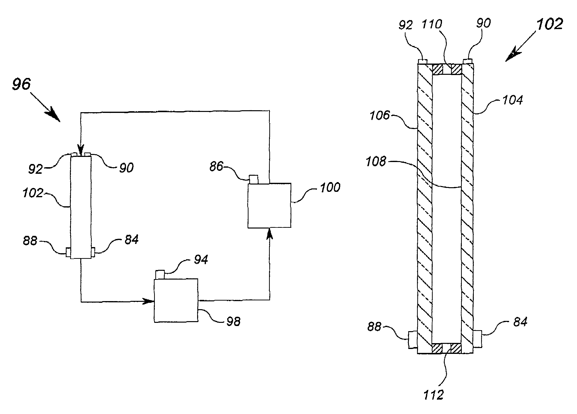
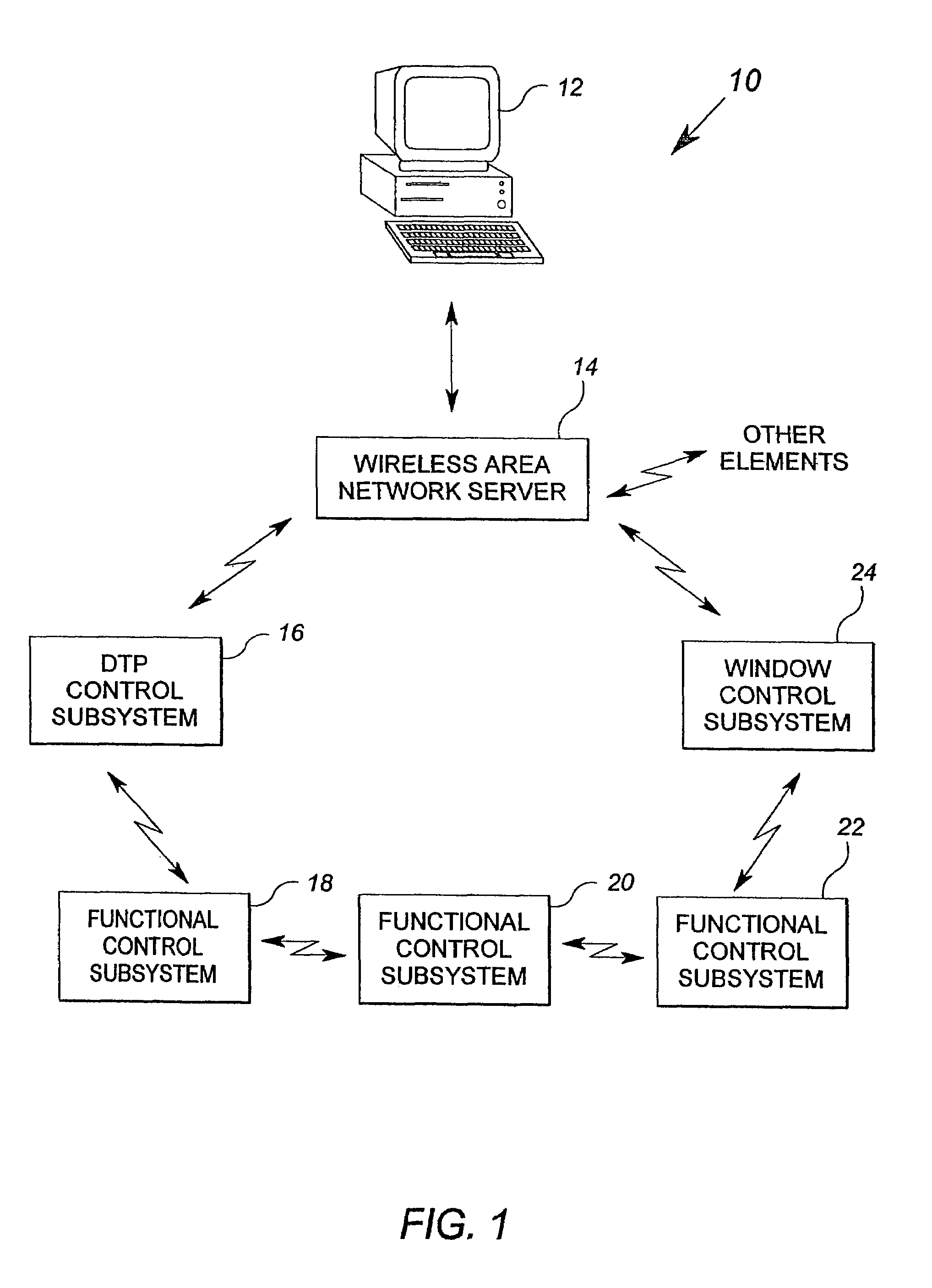
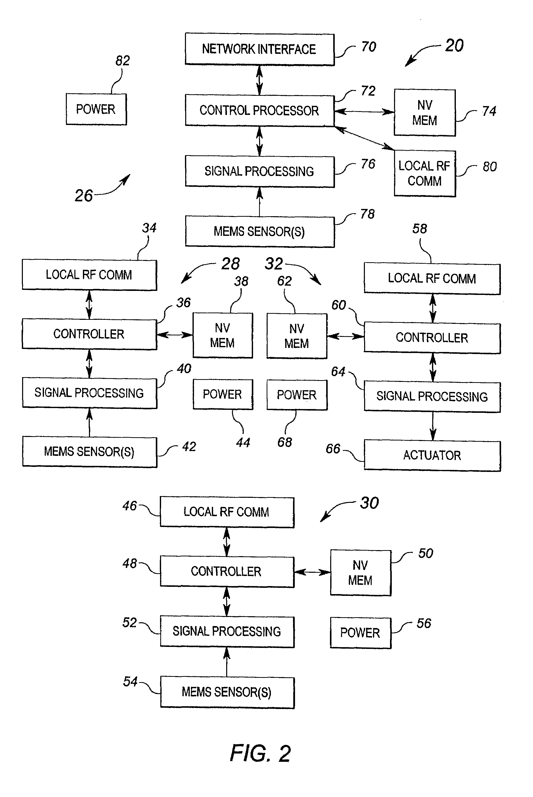
[0038]FIG. 1 shows a block diagram of an exemplary building control system in accordance with the present invention. The building control system 10 includes a supervisory computer 12, a wireless area network (WAN) server 14, a distributed thermal plant (DTP) control subsystem 16, three functional control subsystems 18, 20 and 22, and a window control subsystem 24. The building control system 10 includes only the few above-mentioned elements for clarity of exposition of the principles of the invention. Typically, many more functional control subsystems, as well as many more window, thermal plant, and other building HVAC subsystems, will be included into a building control network. Those of ordinary skill in the art may readily incorporate the methods and features of the invention described herein into control systems of larger or smaller scale.

[0039]In general, the building control system 10 employs a first wireless communication scheme to effect communications between the supervisor...


PUM

PropertyMeasurementUnit
temperatureaaaaaaaaaa
areaaaaaaaaaaa

Abstract

A building component system includes a building component that is controllable between a first state and a second state in response to a sensed condition. The system may include a sensor on a first side of the building component and a sensor on the second side of the building component. The building component may be a window that is controllable between an opaque state and a clear state by a micro electromechanical system (MEMS) network that senses the conditions on both sides of the window.

Description

[0001]This application claims the benefit of and / or priority to U.S. provisional application Ser. No. 60 / 556,119, filed Mar. 25, 2004.FIELD OF THE INVENTION[0002]The present invention relates generally to control systems, such as control systems used to control heating, ventilation, air conditioning, fire safety, lighting, security and other systems or machinery of a building or facility.BACKGROUND OF THE INVENTION[0003]Heating, ventilation and air-conditioning (“HVAC”) systems are used in all types of commercial, industrial and residential facilities (hereinafter referred to as “buildings”). In general, the HVAC system is designed to maintain various predetermined set points, such as temperature. To that end, a system that generates hot air may be controlled on or off depending on the need for heat in a particular location. The supply of conditioned air (hot or cold) may further be controlled by the use of dampers within the air supply system. In larger buildings, the dampers may b...

Claims


Application Information

Patent Timeline
Patent Type & Authority Patents(United States)
IPC IPC(8): E06B3/66F24J2/40G01K7/00F24F7/00F24F11/00F25D17/02
CPCF24F11/001F24F11/0086Y02B10/20F24F11/30F24F2110/00F24F11/52F24F11/875
Inventor AHMED, OSMAN
Owner SIEMENS IND INC
Learn More