Eureka AIR delivers breakthrough ideas for toughest innovation challenges, trusted by R&D personnel around the world.

Gear cutting simulation method, gear cutting simulation program, and gear cutting simulation device

a simulation program and gear cutting technology, applied in the direction of electric programme control, program control, instruments, etc., can solve the problems of difficulty in carrying out simulation, uncertain how the gear cutting conditions, gear geometry value, etc., should be changed in order to create the gear that can withstand the actual use, and difficulty in obtaining the proper tooth contact state by actually changing parameters according to the guidelin

Inactive Publication Date: 2009-10-06
SUMITOMO HEAVY IND LTD
View PDF17 Cites 9 Cited by
  • Summary
  • Abstract
  • Description
  • Claims
  • Application Information

AI Technical Summary

Benefits of technology

The present invention provides an improved gear cutting simulation method and device that can accurately simulate the gear cutting process. The method and device create a 3D gear model with the same configuration as the actual gear, allowing for the analysis of tooth-contact state and the evaluation of gear model validity. The method and device can also automatically adjust the gear cutting conditions based on the results of the tooth-contact state analysis, making the gear cutting simulation process more efficient and accurate. Additionally, the method and device can create a gear heat-treatment model and surface-treatment model to further enhance the accuracy of the gear cutting simulation.

Problems solved by technology

Moreover, it is known that it is difficult to carry out the simulation in the case of hypoid gears because of the particulars of the tooth form.
However, when the satisfactory analysis result is not obtained by using the above-mentioned methods, there is the problem in that it is uncertain how the gear cutting conditions, the gear geometry value, etc. should be changed in order to create the gear that can withstand the actual use.
Although the system of Gleason Co. provides the guideline for changing such parameters, it is difficult to obtain the proper tooth-contact state by actually changing the parameters according to the guideline.

Method used


Image

  • Gear cutting simulation method, gear cutting simulation program, and gear cutting simulation device
  • Gear cutting simulation method, gear cutting simulation program, and gear cutting simulation device
  • Gear cutting simulation method, gear cutting simulation program, and gear cutting simulation device

Examples


Embodiment Construction

[0063]A description will now be provided of the preferred embodiments of the present invention with reference to the accompanying drawings.

[0064]In the following embodiments, the gear cutting simulation of hypoid gear set will be explained as an example.

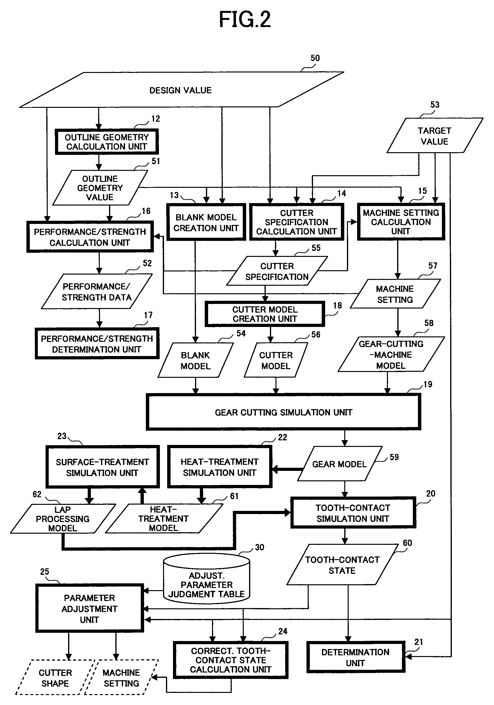
[0065]FIG. 1 shows the hardware composition of the gear cutting simulation device 10 in the preferred embodiment of the invention.

[0066]The gear cutting simulation device 10 of FIG. 1 comprises the drive device 100, the storage medium 101, the auxiliary storage 102, the memory device 103, the computation device 104, the display device 105, and the input device 106, which are interconnected by the bus B.

[0067]The gear cutting simulation program which is used by the gear cutting simulation device 10 is supplied by the storage medium 101, such as CD-ROM. The storage medium 101 in which the gear cutting simulation program is recorded is set in the drive device 100, and the gear cutting simulation program is installed in the auxiliary sto...


PUM


Abstract

In a gear cutting simulation method and device, a gear-cutting-machine model which specifies relative positions between a blank model and a cutter model is created. A gear model is created as a result of simulation of gear cutting which is performed with the blank model and the cutter model arranged in the gear-cutting-machine model.

Description

CROSS-REFERENCE TO RELATED APPLICATION[0001]This application is based upon Japanese Patent Application No. 2002-249678, which was filed on Aug. 28, 2002 and laid open as Japanese Laid-Open Patent Application No. 2004-086773 on Mar. 18, 2004, the entire contents of which are incorporated herein by reference.BACKGROUND OF THE INVENTION[0002]1. Field of the Invention[0003]The present invention generally relates to computer-based simulation method and device, and more particularly to computer-based gear cutting simulation method and device.[0004]2. Description of the Related Art[0005]Conventionally, there have been many approaches for analyzing the gear cutting state and engagement condition, in order to reduce the load of the actual gear cutting work or the design operation.[0006]For example, Japanese Laid-Open Patent Application No. 9-212222 discloses the method of checking the interference of the tool and the gear and the interference of the gears in the engagement relation by carryi...

Claims


Application Information

Patent Timeline
Patent Type & Authority Patents(United States)
IPC IPC(8): G06G7/48G06G7/64B23F23/12G05B19/18G05B19/4069G06F17/50
CPCG05B19/186G05B2219/36198G05B2219/35346
Inventor SHIGEMI, TAKAOYAMAMOTO, AKIRA
Owner SUMITOMO HEAVY IND LTD
Why Eureka
Eureka Blog
Learn More