
Structure element for an aircraft

a technology of structural elements and aircraft, which is applied in the direction of aircraft floors, aircraft frames, generators/motors, etc., can solve the problems of significant noise suppression in the cabin, dampening of etc., to reduce deformation of the fuselage, dampen vibrations in the fuselage, and stabilize the fuselage

Inactive Publication Date: 2009-10-06
AIRBUS OPERATIONS GMBH
View PDF21 Cites 5 Cited by
  • Summary
  • Abstract
  • Description
  • Claims
  • Application Information

AI Technical Summary

Benefits of technology

The present invention provides an improved structural element for aircraft that can stiffen the fuselage, reduce deformation, and dampen vibrations in the fuselage. This is achieved by an active element that can be controlled or regulated to introduce forces into the passive element. The active element can be designed to counteract any bending or deformation of the fuselage caused by external loads. The structural element can also be integrated into the floor structure, frame, transverse girder, or Samer rod for active vibration reduction or dampening. The invention also includes electrical contacts for measuring the force generated by the active element and evaluation electronics for generating a control or regulating signal for the active element. The method for active structuring of aircraft allows for quick and simple weight-neutral improvement in comfort by controlling or regulating the deformation of the fuselage or dampening vibrations.

Problems solved by technology

By providing high-performance fast regulating electronics, vibrations in the fuselage may be dampened, which in particular results in significant noise suppression in the cabin.

Method used


Image

  • Structure element for an aircraft
  • Structure element for an aircraft

Examples


Embodiment Construction

[0025]In the following description of the figures, the same reference characters are used for identical or similar elements.

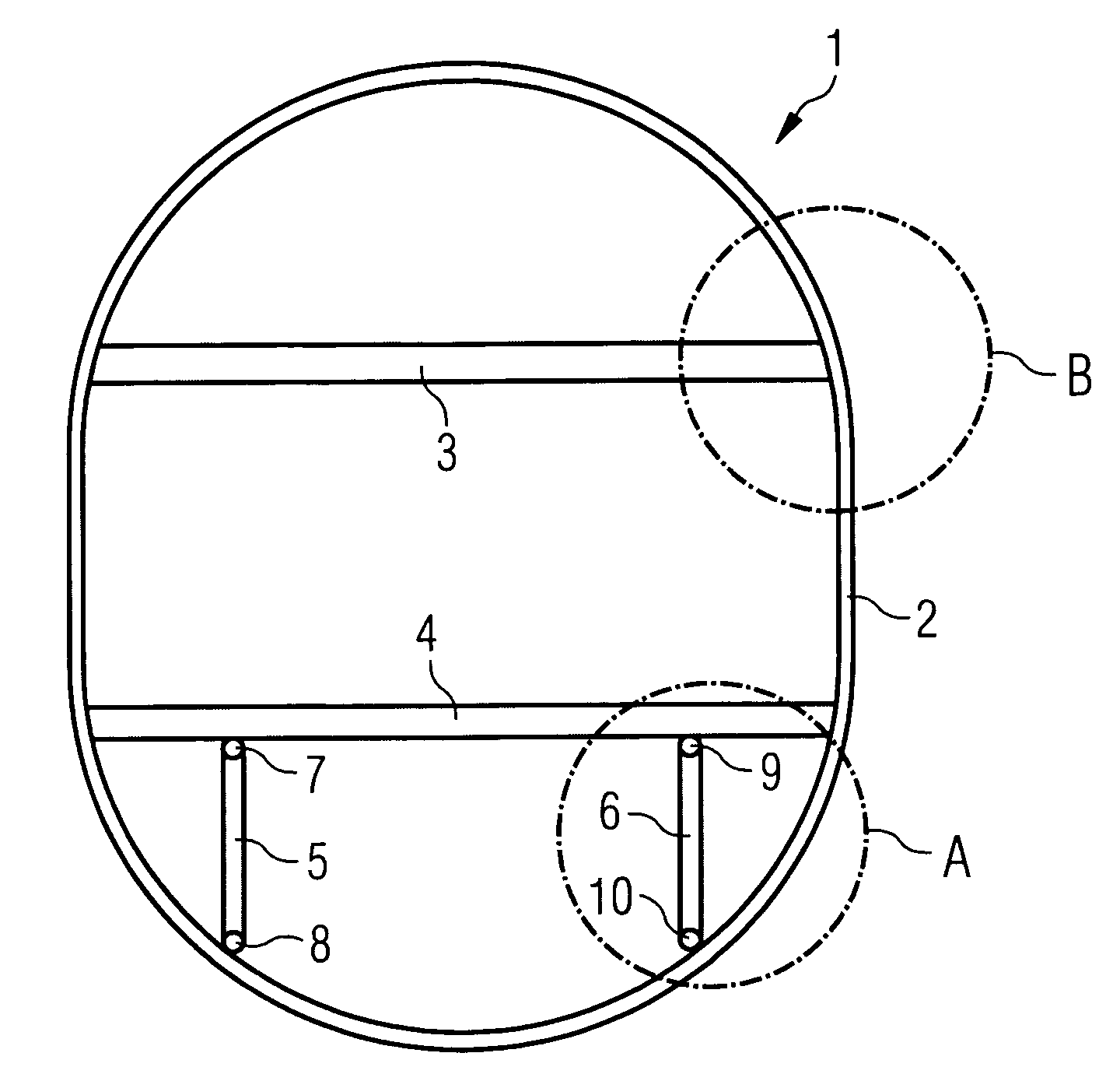
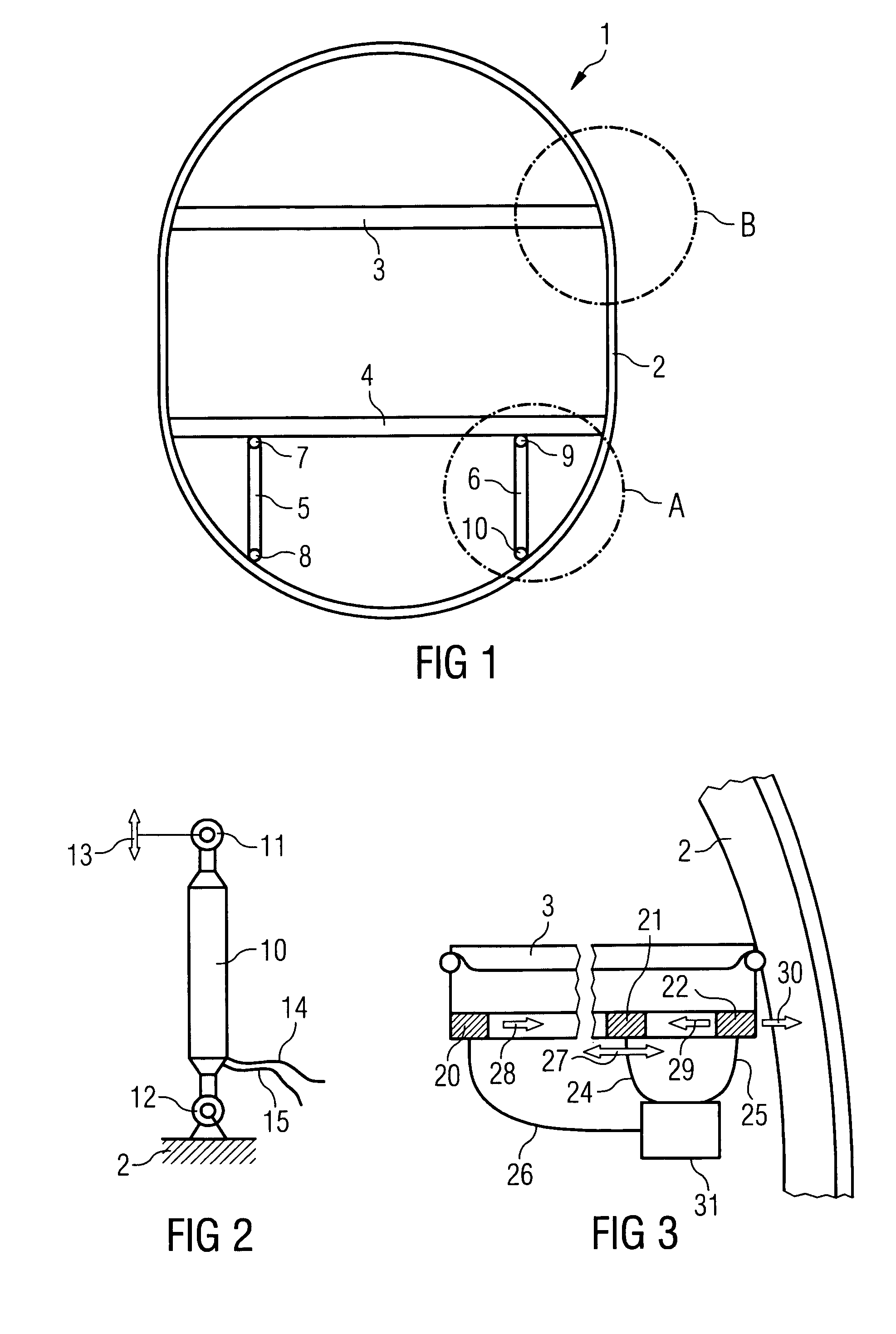
[0026]FIG. 1 shows a diagrammatic cross-sectional representation of a fuselage. As is shown in FIG. 1 the fuselage 1 comprises an external skin 2 that is stabilised, supported and reinforced by transverse girders 3, 4 and Samer rods 5, 6. On the right-hand and left-hand sides the transverse girders 3, 4, which bear the floor structures in the fuselage, are connected to the aircraft frame (not shown in FIG. 1) by way of rivets. The Samer rods 5, 6 are used to support the transverse floor girder 4 downward on the frame. This construction is designed to achieve as stiff a floor as possible.

[0027]As a result of wind gusts or as a result of the engines, at times considerable forces are introduced into the aircraft structure, which forces can for example cause undesirable resonance oscillations or vibrations. These vibrations can at times cause significant noise load...


PUM


Abstract

Nowadays floor structures in the fuselage of airplanes, which floor structures comprise transverse floor girders, are usually connected to the frame on the right and left by means of rivets and are in turn supported vertically downward by the frame by way of Samer rods. According to one embodiment of the present invention a structural element for an aircraft is stated, comprising an active element and a passive element. In this way additional stiffening of the fuselage, a reduction in fuselage deformation, or active vibration dampening can be provided without additional weight.

Description

CROSS-REFERENCE TO RELATED APPLICATIONS[0001]This application claims the benefit of the filing date of U.S. Provisional Patent Application No. 60 / 644,824 filed Jan. 18, 2006, the disclosure of which is hereby incorporated herein by reference.BACKGROUND OF THE INVENTION[0002]The present invention relates to active structural elements of aircraft. In particular, the present invention relates to a structural element for an aircraft, comprising an active element and a passive element, an aircraft comprising a corresponding structural element, the use of a structural element in an aircraft, and a method for the active structuring of aircraft.[0003]In the fuselage of aeroplanes, floor structures that comprise transverse floor girders and seat rails are connected to the frame on the right and left by means of rivets and are in turn supported vertically downward by the frame by way of so-called Samer rods. In this arrangement the seat rails extend transversely over the transverse girders. T...

Claims


Application Information

Patent Timeline
Patent Type & Authority Patents(United States)
IPC IPC(8): H01L41/08H10N30/00
CPCB64C1/06B64C1/40B64C1/18
Inventor FRANKENBERGER, ECKARTKONSTANZER, PETER
Owner AIRBUS OPERATIONS GMBH
Learn More