
System and method for built-in testing of a GPS receiver

a technology for gps receivers and built-in testing, which is applied in the field of built-in testing of gps receivers, can solve problems such as increasing difficulty in achieving sufficient test coverage, affecting the accuracy of built-in testing, and insufficient prior art ability to provide built-in testing of these technologies

Active Publication Date: 2009-09-29
TRIMBLE NAVIGATION LTD
View PDF11 Cites 4 Cited by
  • Summary
  • Abstract
  • Description
  • Claims
  • Application Information

AI Technical Summary

Benefits of technology

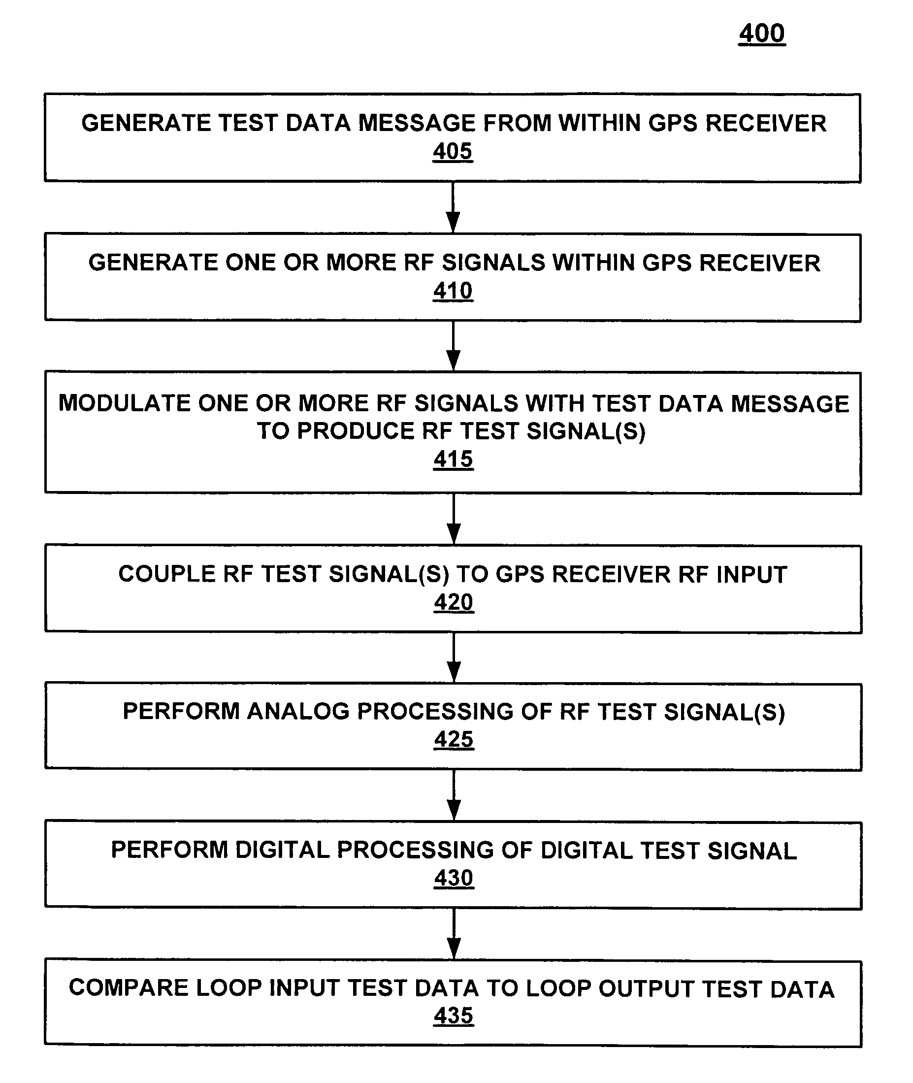
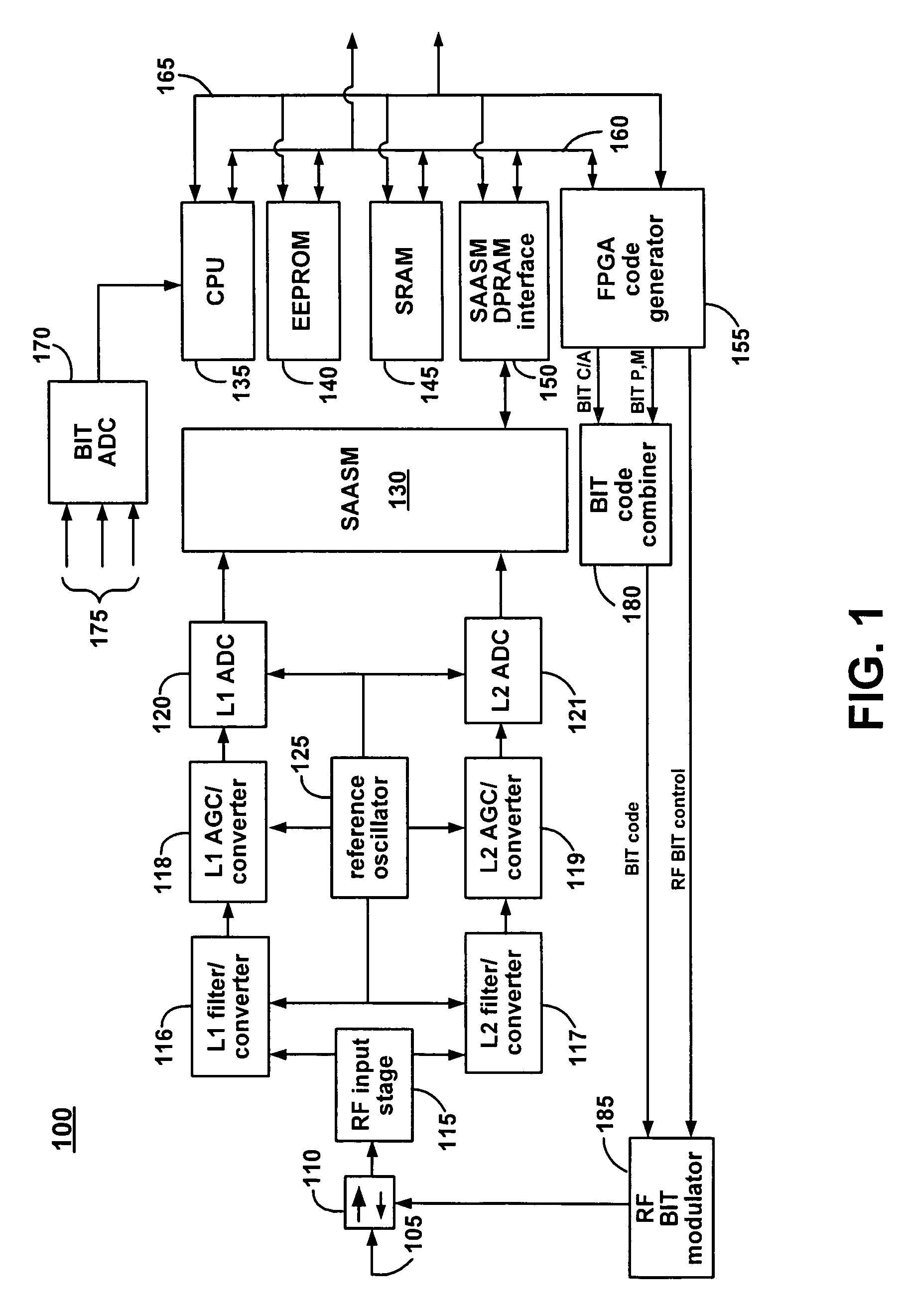
[0007]Accordingly, the present invention provides a system and method for built-in testing of a global positioning system (GPS) receiver. Embodiments of the present invention provide a loop forward capability and a loop backward capability that in combination provide a comprehensive BIT capability for both the analog and digital portions of the signal path in a GPS receiver.
[0009]In another embodiment, a loop backward BITE is used by a system processor in a GPS receiver to sample the positioning data and output by the GPS receiver. The microprocessor also controls a loop forward BITE, thus providing comprehensive testing of the signal path within the GPS receiver.

Problems solved by technology

In civil aircraft operations where system safety is a paramount concern, it important that GPS receivers not be allowed to operate in a defective fashion that outputs potentially hazardous and misleading information (HMI) to a pilot.
As GPS receivers become more complex, the difficulty in achieving sufficient test coverage increases.
However, the ability to provide built-in testing of these technologies is lacking in the prior art.

Method used


Image

  • System and method for built-in testing of a GPS receiver
  • System and method for built-in testing of a GPS receiver
  • System and method for built-in testing of a GPS receiver

Examples


Embodiment Construction

[0016]Reference will now be made in detail to the preferred embodiments of the invention, examples of which are illustrated in the accompanying drawings. While the invention will be described in conjunction with the preferred embodiments, it will be understood that they are not intended to limit the invention to these embodiments. On the contrary, the invention is intended to cover alternatives, modifications and equivalents, which may be included within the spirit and scope of the invention as defined by the appended claims. Furthermore, in the following detailed description of the present invention, numerous specific details are set forth in order to provide a thorough understanding of the present invention. However, it will be obvious to one of ordinary skill in the art that the present invention may be practiced without these specific details. In other instances well known methods, procedures, components, and circuits have not been described in detail as not to unnecessarily obs...


PUM


Abstract

Built-in test equipment (BITE) incorporated in a GPS receiver for providing a loop forward test. The loop forward test capability may be combined with a loop backward capability to provide a comprehensive built-in test (BIT) capability for the signal path in a GPS receiver. A code generator generates deterministic test code signals such as C / A code, P code and pseudo M code that are used to modulate one or more radio frequency (RF) carriers to produce RF test signals. The RF test signals are injected into the GPS receiver's RF input. The RF test signal signals are then down-converted and demodulated through an operational signal path of the GPS receiver. The processed test signals may then be compared to the initial test data. A loop backward BITE may also be used to sample the positioning data output by the receiver.

Description

FIELD OF THE INVENTION[0001]The present claimed invention relates to the field of global positioning system (GPS) instruments. More particularly, the present claimed invention relates to built-in testing of GPS instruments.BACKGROUND ART[0002]In civil aircraft operations where system safety is a paramount concern, it important that GPS receivers not be allowed to operate in a defective fashion that outputs potentially hazardous and misleading information (HMI) to a pilot. Thus, the probability of a GPS receiver outputting such information is typically specified (e.g., less than 10−5 per flight hour) by regulations governing civil aviation.[0003]The Federal Aviation Administration (FAA) has developed certification procedures for GPS airborne receivers using the Standard Positioning Service (SPS) for Instrument Flight Rules (IFR) operation in the National Airspace System (NAS), embodied in Technical Standard Orders (TSOs) C129a, C145, and C146. The certification of a GPS airborne rece...

Claims


Application Information

Patent Timeline
Patent Type & Authority Patents(United States)
IPC IPC(8): G06F19/00G01S1/00
CPCG01S19/23G01S19/32
Inventor RISTAU, RANDALL DALETURNEY, PAUL
Owner TRIMBLE NAVIGATION LTD
Learn More