
Machine for balancing vehicle wheels

a technology for balancing machines and wheels, which is applied in the direction of transportation and packaging, instruments, and static/dynamic balance measurement, etc., can solve the problems of difficult or practical operation, difficult movement/orientation devices, and often complicated working of traditional balancing machines

Inactive Publication Date: 2009-09-29
SICAM SRL
View PDF7 Cites 6 Cited by
  • Summary
  • Abstract
  • Description
  • Claims
  • Application Information

AI Technical Summary

Benefits of technology

[0008]The main aim of this invention is to devise a machine for balancing vehicle wheels that makes it possible to achieve the above mentioned improvements and which allows, in particular, the detection of the position of the ring-shaped flanges on the wheel rim simply without the need for complex mechanisms, and without taking the tire off its rim and then putting the tire back on the rim.
[0009]As part of such technical aim, another purpose of the present invention is to achieve the previous aims with a simple structure, capable of relatively practical implementation, safe in use and effective in operation, and at a relatively low cost.

Problems solved by technology

As a matter of fact, a pair of feelers and / or a sensor movement / orientation device can often complicate considerably the working of traditional balancing machines.
The fact that the tire has to be taken off or removed, and then put back on the wheel is an additional, and inconvenient operation, that is not always easy or practical to perform.

Method used


Image

  • Machine for balancing vehicle wheels
  • Machine for balancing vehicle wheels
  • Machine for balancing vehicle wheels

Examples


Embodiment Construction

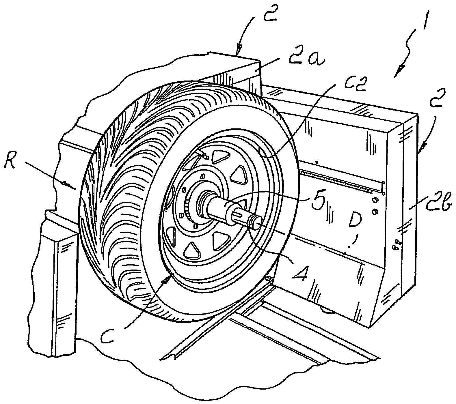
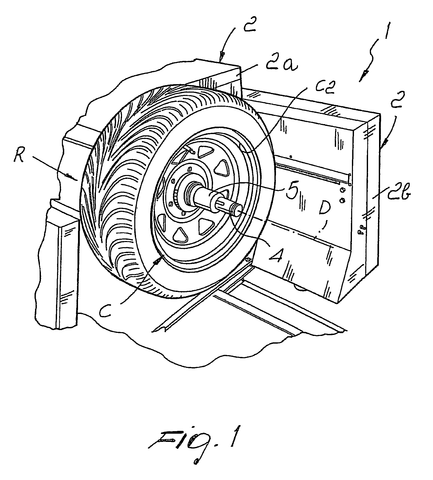
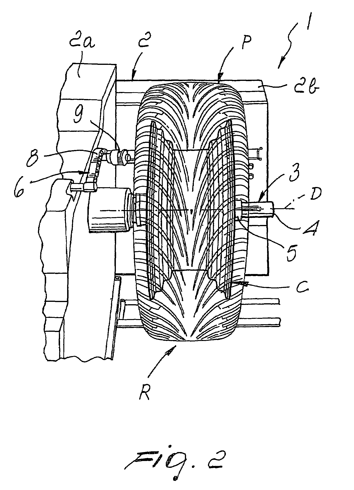
[0017]With special reference to such figures, a machine for balancing vehicle wheels has been generally designated by reference numeral 1.

[0018]The machine 1 comprises a frame 2 that supports the gripping and rotation means 3 for a wheel R to be balanced around a horizontal axis D.

[0019]In particular, the frame 2 is made up of a base block 2a that contains the supporting and motorisation system of the gripping and rotation means 3, and of a vertical wall 2b associated with one side of the base block 2a.

[0020]The gripping and rotation means 3 are composed of a shaft 4, that defines the axis D and extends from the base block 2a parallel with the vertical wall 2b, and a bush 5, movable along the free end of the shaft 4 for centering and fixing the rim C of the wheel R.

[0021]When the wheel R is mounted on the shaft 4, a first ring-shaped flange C1 of the rim C is alongside the base block 2a while the second ring-shaped flange C2, opposite the first, is turned towards the outside of the...


PUM


Abstract

A machine for balancing vehicle wheels, such wheels including a rim with a pair of axially spaced, ring-shaped or annular, flanges, and a tire seated up on the rim. The machine includes a frame with motor driven devices for gripping the vehicle wheel to be balanced and rotating same about a horizontal axis. A mechanical feeler, or probe, determines the position of the first of the pair of , flanges on the rim. A contact-less, or remotely spaced, sensor, such as a laser, ascertains the profile of the tire by taking a series of discrete measurements without touching the tire. The mechanical feeler, or probe, and the contact-less sensor, are connected to a control unit in the machine. The control unit interpolates the values provided by the mechanical feeler and the contact-less sensor, and determines the location of the second flange on the wheel rim. The control unit may include an archive, or database, of the dimensions of known rims, to facilitate the accurate determination of the location of the second flange, on the wheel rim.

Description

BACKGROUND OF THE INVENTION[0001]The present invention refers to a machine for balancing vehicle wheels.[0002]To this end, known balancing machines are usually equipped with a pair of mechanical feelers which can be positioned adjacent both ring-shaped flanges so their positions can be detected.[0003]Alternatively, it is common practice to replace the two feelers with a contact-less measuring sensor (laser, ultrasound or the like), fitted with a movement and orientation device, so it can be aimed at the tire and at the rim so the position of the ring-shaped flanges can be detected without having to remove / fit the tire from / on the wheel rim.[0004]Other types of balancing machines are equipped with a contact-less sensor alongside the wheel tread which normally detects any unevenness on the tire. However, if this type of sensor is required to detect the position of the ring-shaped flanges on the wheel rim, the tire has to be removed from the wheel so the rim can be inspected correctly....

Claims


Application Information

Patent Timeline
Patent Type & Authority Patents(United States)
IPC IPC(8): G01M1/16
CPCG01M1/326G01M1/02
Inventor MATTEUCCI, MARCOMONTANARI, MARCONICOLINI, ROBERTO
Owner SICAM SRL
Learn More