System and method for the fixation of bone fractures

a bone fracture and fixation system technology, applied in the field of lagwire system, can solve the problems of very time-consuming, each step and the entire process is very time-consuming, and the insertion of existing screws through or around fractures has disadvantages, so as to facilitate the fixation of bone fractures, facilitate the change of distance between objects, and facilitate the effect of the change of distan

Inactive Publication Date: 2009-09-22
ORTHOIP
View PDF63 Cites 193 Cited by
  • Summary
  • Abstract
  • Description
  • Claims
  • Application Information

AI Technical Summary

Benefits of technology

[0006]In general, the invention facilitates the fixation of bone fractures. In a particular embodiment, the head component includes a tip, cutting threads and mating threads which are inserted into the far cortex of the bone. A wire extends from the head component and exits from the near cortex. A cap device having a sawtooth inner surface is threaded over the wire having an inverse sawtooth outer surface such that the cap is restricted from backwards movement. Tension is then applied to the wire while the cap is tightened against or within the bone surface to thereby apply an appropriate amount of pressure between the surfaces of the fracture. The excess wire beyond the cap can then be removed.

Problems solved by technology

However, the insertion of existing screws through or around fractures has disadvantages.
For example, the entire process is very time-consuming because inserting a regular screw usually involves multiple steps such as drilling the pilot hole, measuring the relevant distances to determine the appropriate screw selection, tapping the hole to establish threads and screwing the screw into the hole.
Again, each step and the entire process is very time-consuming.
In addition to the length and complexity of the process, the prior art system also typically includes inadequate components.
For example, in poor bone, prior art screws often loose their grip and strip out of the bone.
Currently available lag screws also typically provide only one side of cortex fixation and are generally not suited for percutaneus surgery.
Moreover, when placing the screws in the bone, the physician may not accurately set the screw into the distal hole or may miss the distal hole completely, thereby resulting in the screw stripping the threads or breaking the bone.
Because the physician typically is unable to accurately determine the type or size of screw needed until the physician enters the bone and measures the appropriate screw placement, operating facilities need to store and make available large inventories of screws.
Furthermore, if cannulated screws are desired, another entire screw set of over one hundred additional screws is often needed.
As such, inventory management of screws is a very large problem for many operating facilities.

Method used


Image

  • System and method for the fixation of bone fractures
  • System and method for the fixation of bone fractures
  • System and method for the fixation of bone fractures

Examples


Embodiment Construction

[0020]The present invention is described herein and includes various exemplary embodiments in sufficient detail to enable those skilled in the art to practice the invention, and it should be understood that other embodiments may be realized without departing from the spirit and scope of the invention. Thus, the following detailed description is presented for purposes of illustration only, and not of limitation, and the scope of the invention is defined solely by the appended claims. The particular implementations shown and described herein are illustrative of the invention and its best mode and are not intended to otherwise limit the scope of the present invention in any way.

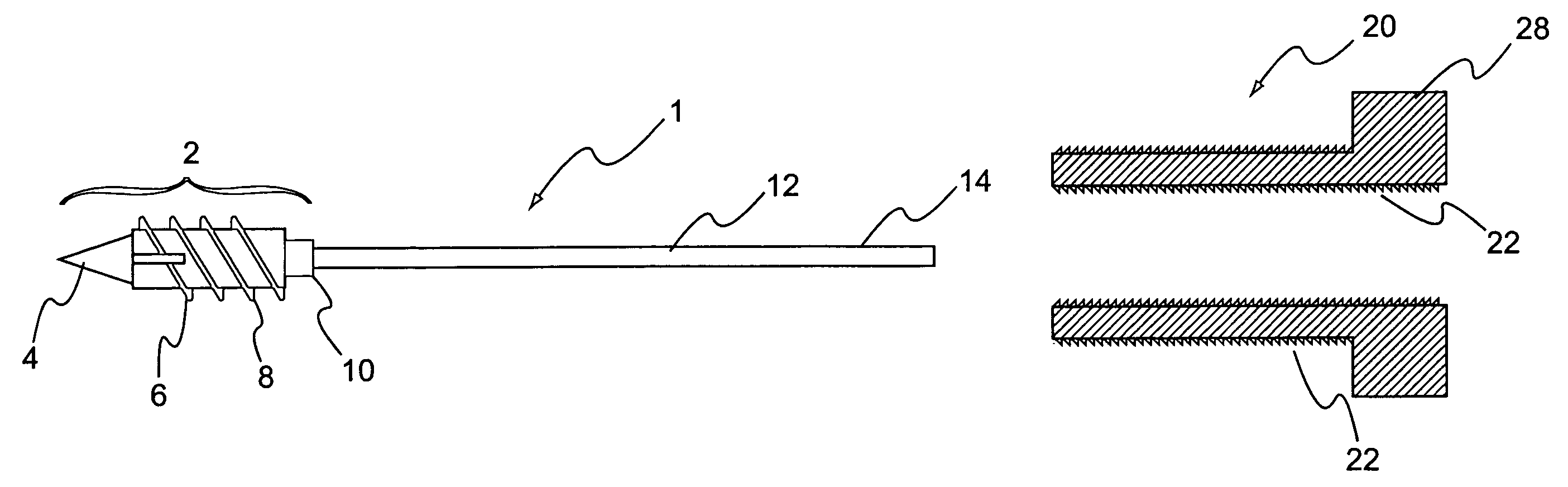
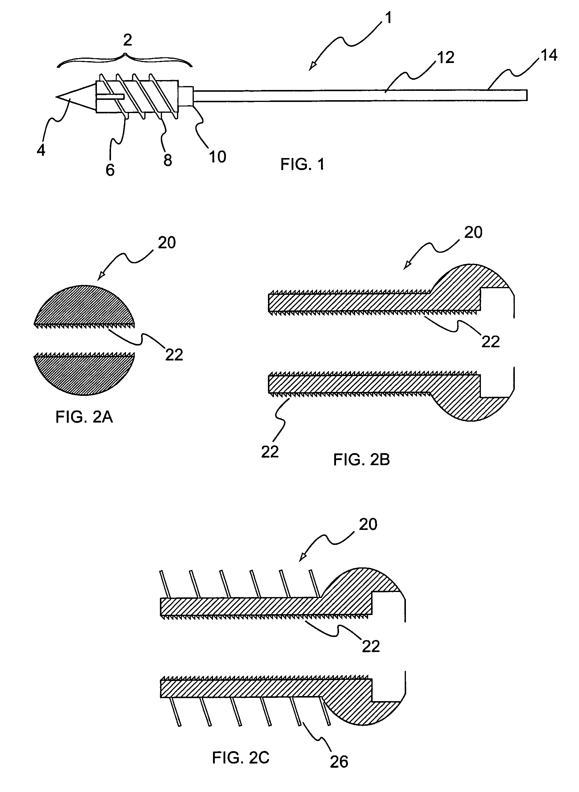
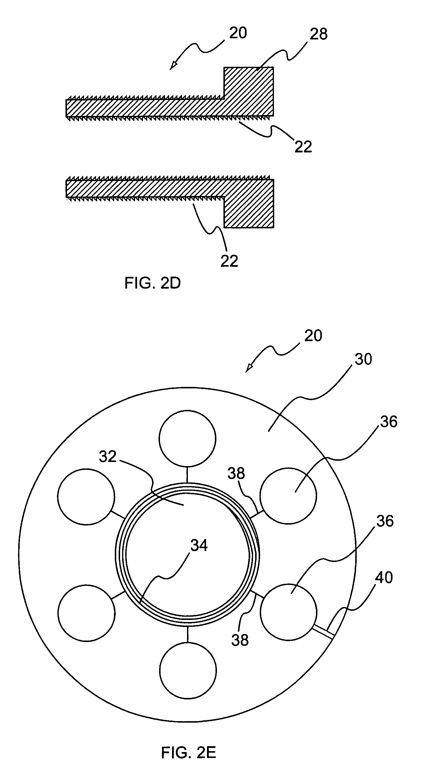
[0021]In general, the present invention facilitates the change in distance between objects or surfaces, compresses objects together and / or provides a configurable or random amount of pressure between surfaces. The system may facilitate changing, maintaining, reducing and / or expanding the distance between objects...


PUM


Abstract

The invention facilitates the fixation of bone fractures. In a particular embodiment, the head component includes a tip, cutting threads and mating threads which are inserted into the far cortex of the bone. A wire extends from the head component and exits from the near cortex. A cap device having a sawtooth inner surface is threaded over the wire having an inverse sawtooth outer surface such that the cap is restricted from backwards movement. Tension is then applied to the wire while the cap is tightened against or within the bone surface to thereby apply an appropriate amount of pressure between the surfaces of the fracture. The excess wire beyond the cap can then be removed.

Description

CROSS-REFERENCE TO RELATED APPLICATIONS[0001]This application claims priority to, and the benefit of, U.S. Ser. No. 10 / 272,773 filed on Oct. 17, 2002 now U.S. Pat. No. 6,736,819 by Kishore Tipirneni, M.D. with the same title, which itself claims priority to U.S. Provisional Application Ser. No. 60 / 330,187, entitled “LAGWIRE SYSTEM AND METHOD” filed Oct. 18, 2001, which is incorporated herein by reference.FIELD OF INVENTION[0002]The invention generally relates to a system and method for the fixation of fractures in one or more objects, and more particularly, to a lagwire system and related components for the fixation of bone fractures.BACKGROUND OF THE INVENTION[0003]It is well-known in the medical arts that constant pressure on a bone fracture speeds healing. As such, orthopedic physicians typically insert one or more screws in the area of the fracture in order to assert constant pressure on the bone fracture. However, the insertion of existing screws through or around fractures has...

Claims


Application Information

Patent Timeline
Patent Type & Authority Patents(United States)
IPC IPC(8): A61B17/58A61B17/86A61B17/62A61B17/68A61B17/74A61B17/84A61B17/88
CPCA61B17/68A61B17/683A61B17/8869A61B17/842A61B17/62A61B17/746A61B17/685
Inventor TIPIRNENI, KISHORE
Owner ORTHOIP
Why Eureka
Try Eureka