
System for and method of generating rotational inputs

a technology of rotation input and input, applied in the field of biometric sensors, can solve the problems of consuming substantial surface real estate on a portable device, ever-smaller devices require efficient ways to collect user input, and limited success in conventional devices, so as to achieve simple algorithms, reduce the footprint, and improve the effect of accuracy

Active Publication Date: 2009-09-08
APPLE INC
View PDF263 Cites 41 Cited by
  • Summary
  • Abstract
  • Description
  • Claims
  • Application Information

AI Technical Summary

Benefits of technology

This approach allows for smaller, more power-efficient devices to accurately determine rotational and linear movements, enabling effective emulation of input devices like steering wheels and pointing devices without the need for large surface areas or complex computations.

Problems solved by technology

A dilemma occurs when these ever-smaller devices require efficient ways to collect user input.
Micro joysticks, navigation bars, scroll wheels, touch pads, steering wheels and buttons have all been adopted, with limited success, in conventional devices.
All these positioning devices consume substantial amounts of valuable surface real estate on a portable device.
Mechanical positioning devices such as joysticks, navigation bars and scroll wheels can wear out and become unreliable.
Their sizes and required movements often preclude optimal ergonomic placement on portable computing platforms.
These computations are not helpful for determining linear motion (e.g., non-rotational movement in the x- and y-directions).
Such a shortcoming makes prior art systems even more inefficient when used in portable devices, in which both rotational and linear movement are required, such as when emulating, respectively, a steering wheel and a pointing device.

Method used


Image

  • System for and method of generating rotational inputs
  • System for and method of generating rotational inputs
  • System for and method of generating rotational inputs

Examples


Embodiment Construction

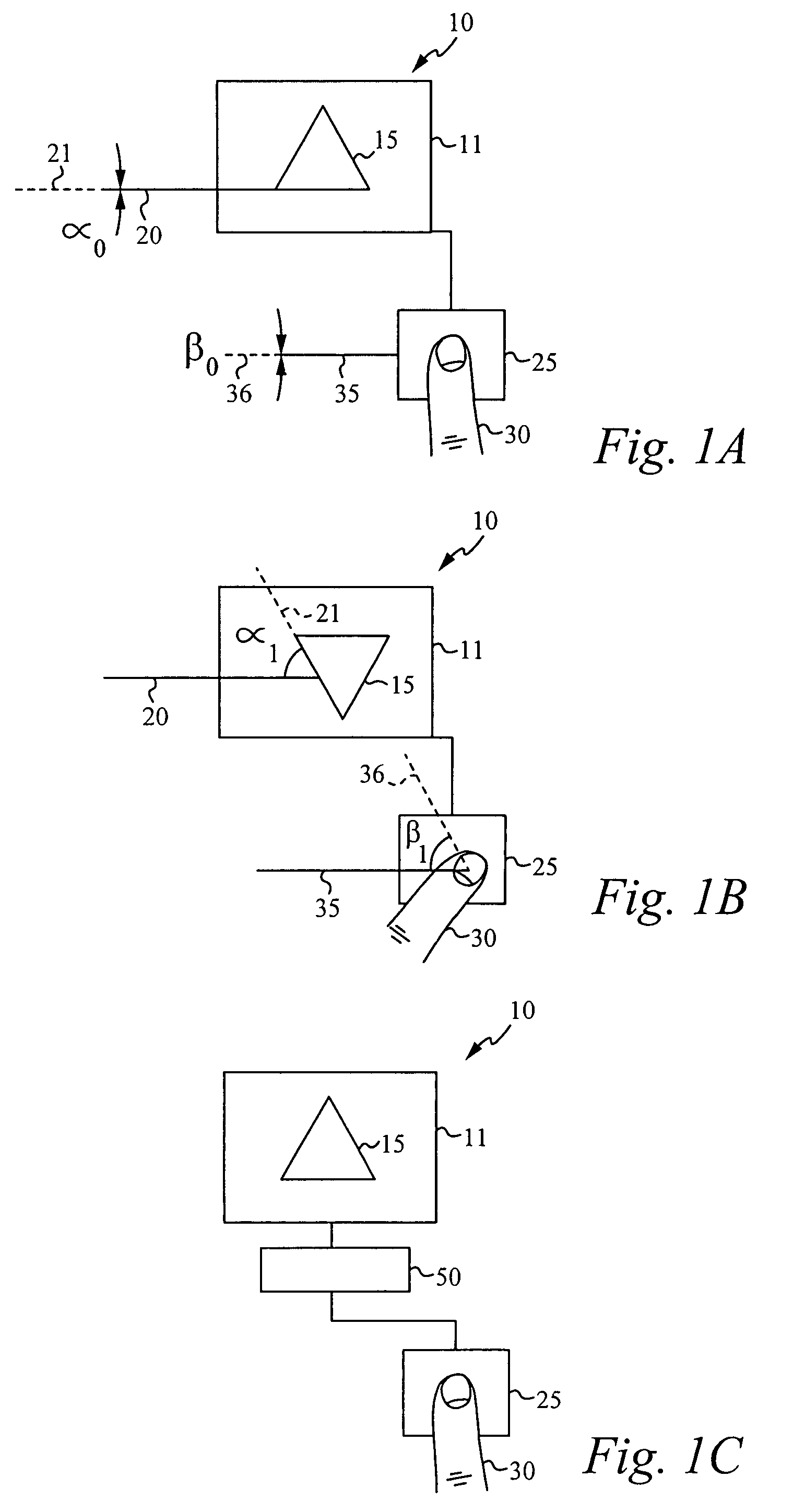
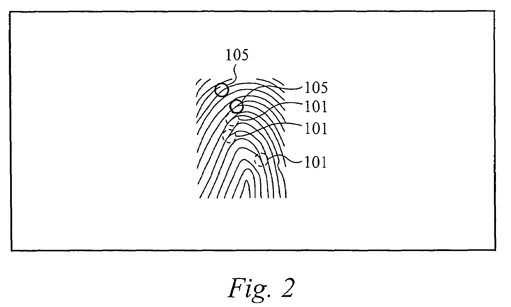
[0031]The present invention is directed to systems for and methods of determining the rotational position and movement of an arbitrary patterned material imaged by an imaging sensor. Preferably, the arbitrary patterned material is a finger and the rotational position and movement of the image of the finger are determined.

[0032]Embodiments of the present invention advantageously determine and collect finger rotational information for use in a digital device and most preferably in personal computing devices. Unlike prior art rotational position correlators, which are non-linear, requiring trigonometric functions like sine, cosine, and tangent calculations, embodiments of the present invention use a linear correlation method that is easier to implement and more computationally efficient. Embodiments of the present invention allow for extremely efficient calculation of linear motion from the components used to determine the rotational motion, thereby reducing the complexity of systems t...


PUM


Abstract

A system for and method of obtaining rotation information is disclosed. The method comprises capturing a plurality of patterned images from a plurality of locations, correlating the plurality of patterned images to generate sets of linear differences, and using the sets of linear differences to generate the rotation information. Preferably, the plurality of locations comprise a first part of a fingerprint swipe sensor and a second part of the fingerprint swipe sensor, each part configured to capture a part of a fingerprint image. Each part captures a part of the fingerprint image at two positions and correlates the parts at the two positions to determine one set of linear differences. Together, the sets of linear differences are used to calculate the rotation information, which can be used to emulate a rotational device such as a steering wheel, a joystick, or a navigation bar.

Description

RELATED APPLICATION[0001]This application claims priority under 35 U.S.C. § 119(e) of the U.S. provisional application Ser. No. 60 / 497,045, filed on Aug. 22, 2003, and titled “ROTATIONAL INPUT METHOD PATENT.” The provisional application Ser. No. 60 / 497,045, filed on Aug. 22, 2003, and titled “ROTATIONAL INPUT METHOD PATENT” is hereby incorporated by reference.FIELD OF THE INVENTION[0002]This invention relates to the field of biometric sensors. In particular, this invention relates to systems and methods that use fingerprint images to emulate electronic positioning devices.BACKGROUND OF THE INVENTION[0003]The emergence of portable electronic computing platforms allows functions and services to be enjoyed wherever necessary. Palmtop computers, personal digital assistants, mobile phones, portable game consoles, biometric / health monitors, remote controls, digital cameras, to name a few, are some daily-life examples of portable electronic computing platforms. The desire for portability h...

Claims


Application Information

Patent Timeline
Patent Type & Authority Patents(United States)
IPC IPC(8): G06K9/00G06F3/033
CPCG06F3/03547G06K9/00026G06F2203/0338G06V40/1335
Inventor RUSSO, ANTHONY P.WEIGAND, DAVID L.
Owner APPLE INC
Learn More