System and method for controlling an error amplifier between control mode changes

Active Publication Date: 2009-09-01
NAT SEMICON CORP
View PDF5 Cites 8 Cited by
  • Summary
  • Abstract
  • Description
  • Claims
  • Application Information

AI Technical Summary

Benefits of technology

[0012]To address the above-discussed deficiencies of the prior art, it is a primary object of the present invention to provide a system and method for improving the performance of an error amplifier when the control mode of the error amplifier is changed.

Problems solved by technology

Circuitry in a DC-DC converter that is capable of providing a high slew rate may not be compatible with achieving a desired level of performance for other circuit elements.
For example, circuitry that enables a high slew rate to be maintained in a DC-DC converter may be in conflict with a design requirement to maintain a low value of bias current.
In DC-DC converter circuits that employ both a pulse frequency modulation (PFM) control mode of operation and a pulse width modulation (PWM) of operation it is difficult to prevent the occurrence of a large transient in the output voltage when the control mode is changed.
The large transient in the output voltage when the control mode is changed is due in large part to the slow operation of the error amplifier of the DC-DC converter.
The relatively large value of capacitance for the capacitor C1 and the relatively small values of the bias currents cause the error amplifier to be relatively slow to respond to the ripple voltage in the output of the DC to DC converter in the pulse frequency modulation (PFM) control mode.

Method used


Image

  • System and method for controlling an error amplifier between control mode changes
  • System and method for controlling an error amplifier between control mode changes
  • System and method for controlling an error amplifier between control mode changes

Examples


Embodiment Construction

[0024]FIGS. 2 through 6 and the various embodiments used to describe the principles of the present invention in this patent document are by way of illustration only and should not be construed in any way to limit the scope of the invention. Those skilled in the art will understand that the principles of the present invention may be implemented in any type of suitably arranged error amplifier circuit.

[0025]To simplify the drawings the reference numerals from previous drawings will sometimes not be repeated for structures that have already been identified.

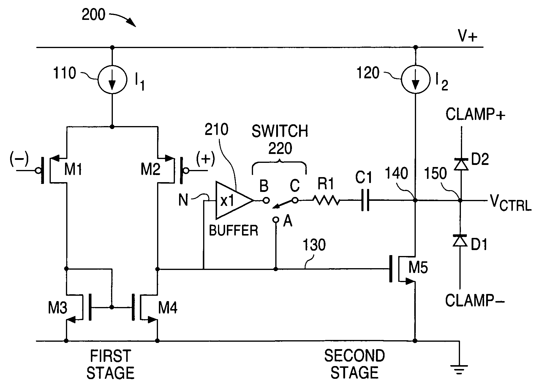
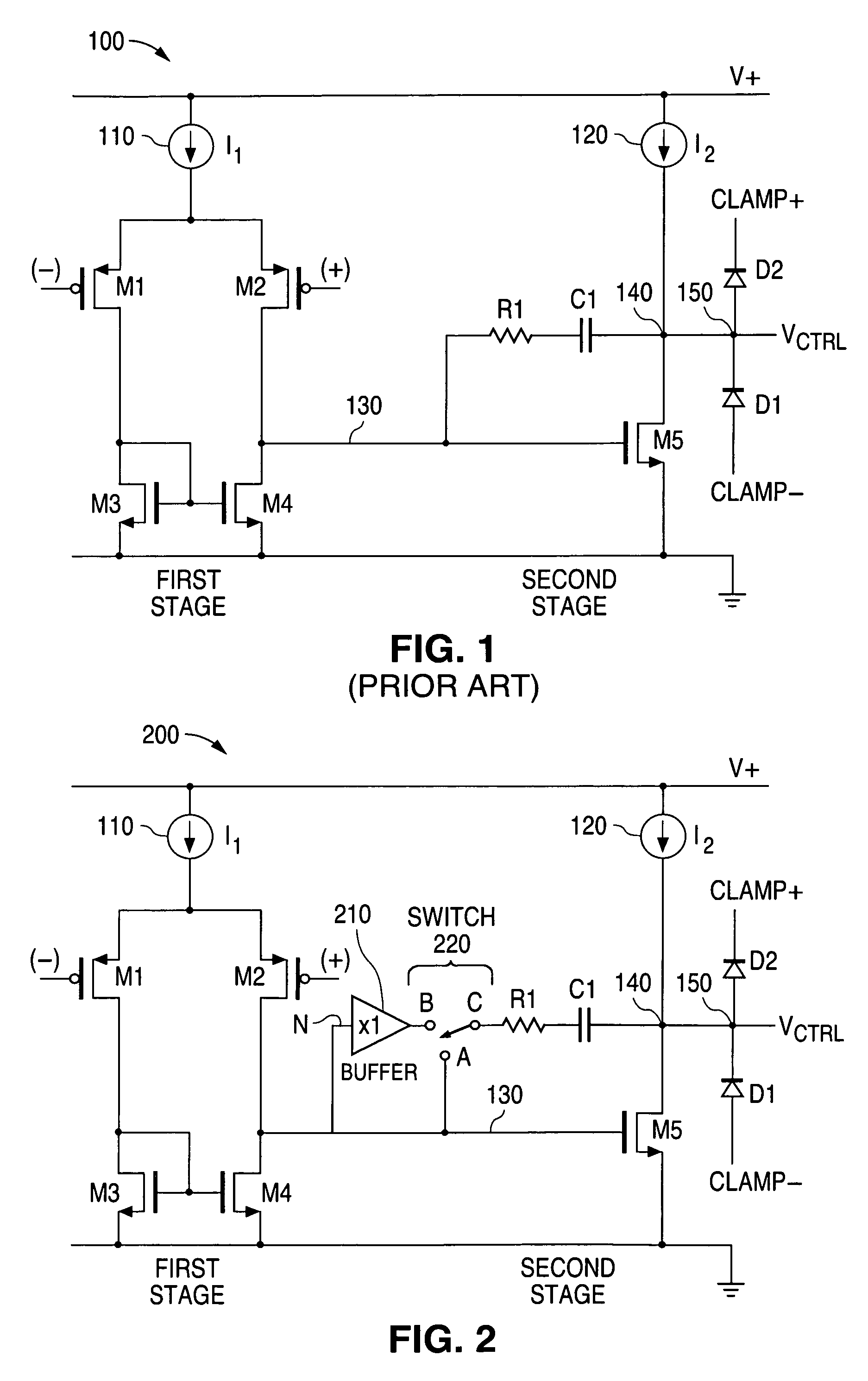
[0026]FIG. 2 illustrates a schematic diagram of an advantageous embodiment of an error amplifier 200 of a direct current (DC) to direct current (DC) converter in accordance with the principles of the present invention. The error amplifier 200 that is shown in FIG. 2 comprises many of the same elements as the prior art amplifier 100 that is shown in FIG. 1. The structure and function of the elements that error amplifier 200 has in com...


PUM


Abstract

A system and a method are disclosed for controlling an error amplifier between control mode changes. An error amplifier comprises a first stage that comprises a first current source and a second stage that comprises a second current source and at least one compensation component that is connected to the first stage through a signal line. A buffer circuit is connected between the signal line and the at least one compensation component and a switch circuit is connected between the buffer circuit and the at least one compensation component. When switched in to the error amplifier the buffer circuit provides a value of current to the at least one compensation component that is larger than a value of current that is provided to the at least one compensation component from the signal line. This increases the slew rate of the error amplifier during a pulse frequency modulation control mode.

Description

TECHNICAL FIELD OF THE INVENTION[0001]The present invention is generally directed to the semiconductor circuits and, in particular, to a system and method for controlling an error amplifier during control mode changes.BACKGROUND OF THE INVENTION[0002]In a switch-mode direct current (DC) to direct current (DC) converter, the error amplifier must slew rapidly when the control mode changes from a pulse frequency modulation (PFM) control mode to a pulse width modulation (PWM) control mode or from a pulse width modulation (PWM) control mode to a pulse frequency modulation (PFM) control mode. The slew rate is the rate of change in output voltage in response to an input signal. It is desirable to have a high value of slew rate.[0003]Circuitry in a DC-DC converter that is capable of providing a high slew rate may not be compatible with achieving a desired level of performance for other circuit elements. For example, circuitry that enables a high slew rate to be maintained in a DC-DC convert...

Claims


Application Information

Patent Timeline
IPC IPC(8): H03F3/38
CPCH03F3/45183H03F2200/411H03F2200/441H03F2203/45728H03F2203/45692H03F2203/45726H03F2203/45674
Inventor DESTASI, FRANKBROACH, MICHAEL EUGENE
Owner NAT SEMICON CORP
Why Eureka
Try Eureka