Dual-diagonal differential space-time code transmitter and receiver

A transmitter and receiver technology, applied in the field of communication transmission, can solve problems such as less than ideal error performance

Inactive Publication Date: 2004-03-10
BEIJING HAPPOK INFORMATION TECH
View PDF0 Cites 0 Cited by
  • Summary
  • Abstract
  • Description
  • Claims
  • Application Information

AI Technical Summary

Problems solved by technology

However, the existing differential space-time code schemes can only be applied to two antennas, or the error performance is not ideal

Method used


Image

  • Dual-diagonal differential space-time code transmitter and receiver
  • Dual-diagonal differential space-time code transmitter and receiver
  • Dual-diagonal differential space-time code transmitter and receiver

Examples


Embodiment Construction

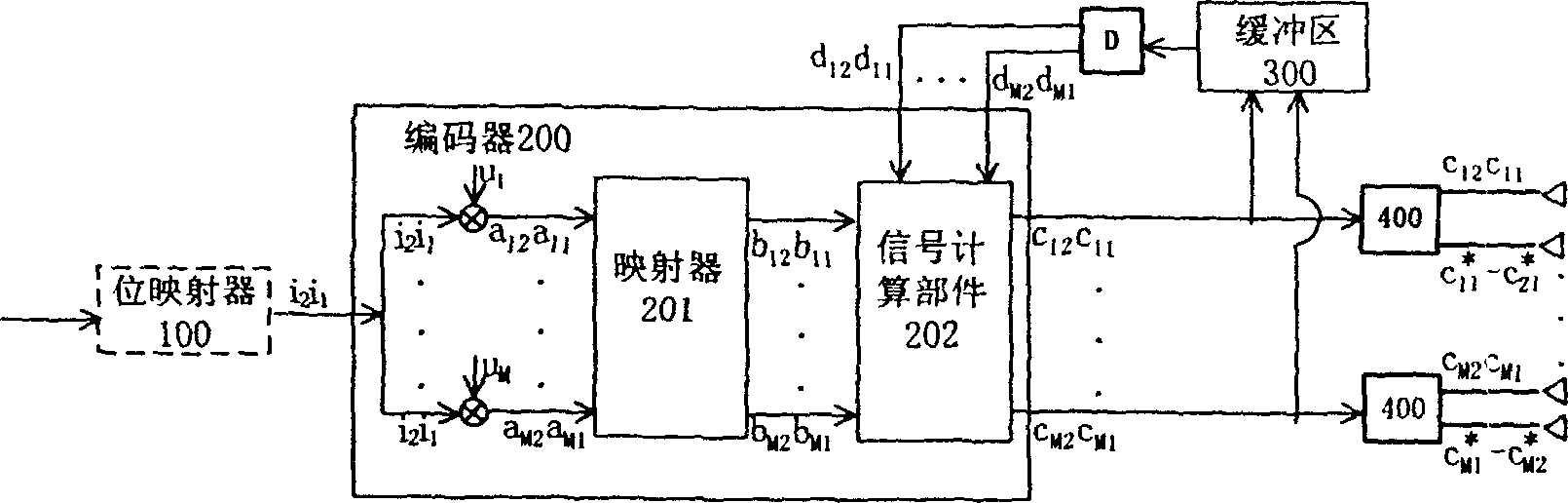
[0008] Such as figure 1 As shown in FIG. 1 , before transmitting a frame of information, the transmitter first sends a set of reference signals, which is called initial transmission. The information of each frame is divided into several groups, each group contains 2MR bits, denoted as j 1 j 2 … j 2MR , they will be sent by 2M transmitting antennas in 2M time slots.

[0009] The process of sending a group is as follows:

[0010] 1) In order to further reduce the bit error rate, a bit mapper 100 can be introduced at the front end of the encoder. The mapping rule is: if j 1 = 1, then for j 2 … j MR The MR-1 bits are inverted. if j MR+1 = 1, then for j MR+1 … j 2MR The MR-1 bits are inverted.

[0011] 2) The input of the encoder is 2 integers i 1 and i 2 , each integer corresponds to MR bits in each group of information. which is i 1 = Σ k = 1 ...


PUM


Abstract

The invention relates to the transmitter and receiver of the bi-diagonal differential space-time code. The transmitter includes the encoder, the buffer and M pieces of the signal imaging assembly with double antenna. Comparing with the existed differential space-time code, the bi-diagonal differential space-time code possesses following advantages of simple transmitter and receiver, fast decoding and obvious improved error performance. The invention provides the diversity transmitting and receiving method by use of the multiple transmitting antennas and the receiving antennas, under condition of both the transmitter and receiver not knowing the channel-fading coefficient. The number of the transmitting antennas is 2M(M>=2), and the number of the receiving antennas is arbitrary.

Description

technical field [0001] The present invention relates to communication transmission, in particular to a transmitter and a receiver of a double-diagonal differential space-time code for an even number greater than or equal to 4 transmitting antennas. Background technique [0002] The fading effect of wireless channels is the biggest obstacle to realize reliable wireless data transmission at high data rates. Space-time coding combines the diversity gain of multiple antennas and the coding gain of channel coding, so that it can effectively resist fading effects and achieve reliable transmission without reducing the data transmission rate. Space-time coding has been adopted by 3GPP. Most of the current studies on space-time coding assume that the receiver can obtain accurate fading coefficients. However, when the fading coefficient changes rapidly, such as when the mobile station is moving at high speed, the cost of channel estimation becomes very high or even impossible. Diff...

Claims


Application Information

Patent Timeline
IPC IPC(8): H04B1/02H04B1/06
Inventor 李舒韩承德
Owner BEIJING HAPPOK INFORMATION TECH
Why Eureka
Try Eureka