
Compression screw apparatuses, systems and methods

a screw and screw technology, applied in the field of screw apparatuses and methods, can solve the problems of preventing successful or optimal outcomes, affecting the functional outcome, and reducing the operative time, so as to achieve the effect of convenient and effective use of compressing suitable materials

Inactive Publication Date: 2009-09-01
INTEGRA LIFESCI
View PDF42 Cites 186 Cited by
  • Summary
  • Abstract
  • Description
  • Claims
  • Application Information

AI Technical Summary

Benefits of technology

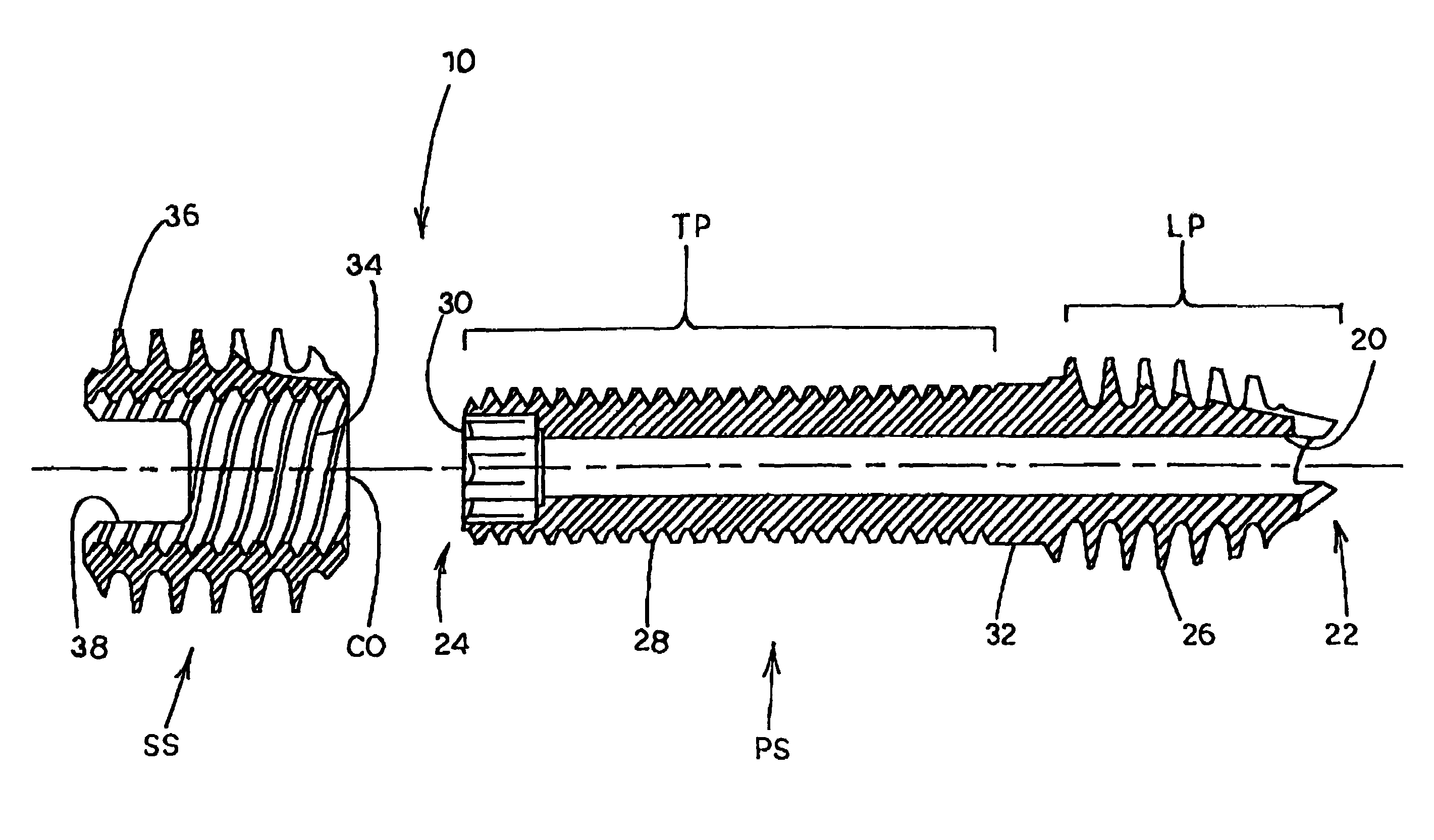
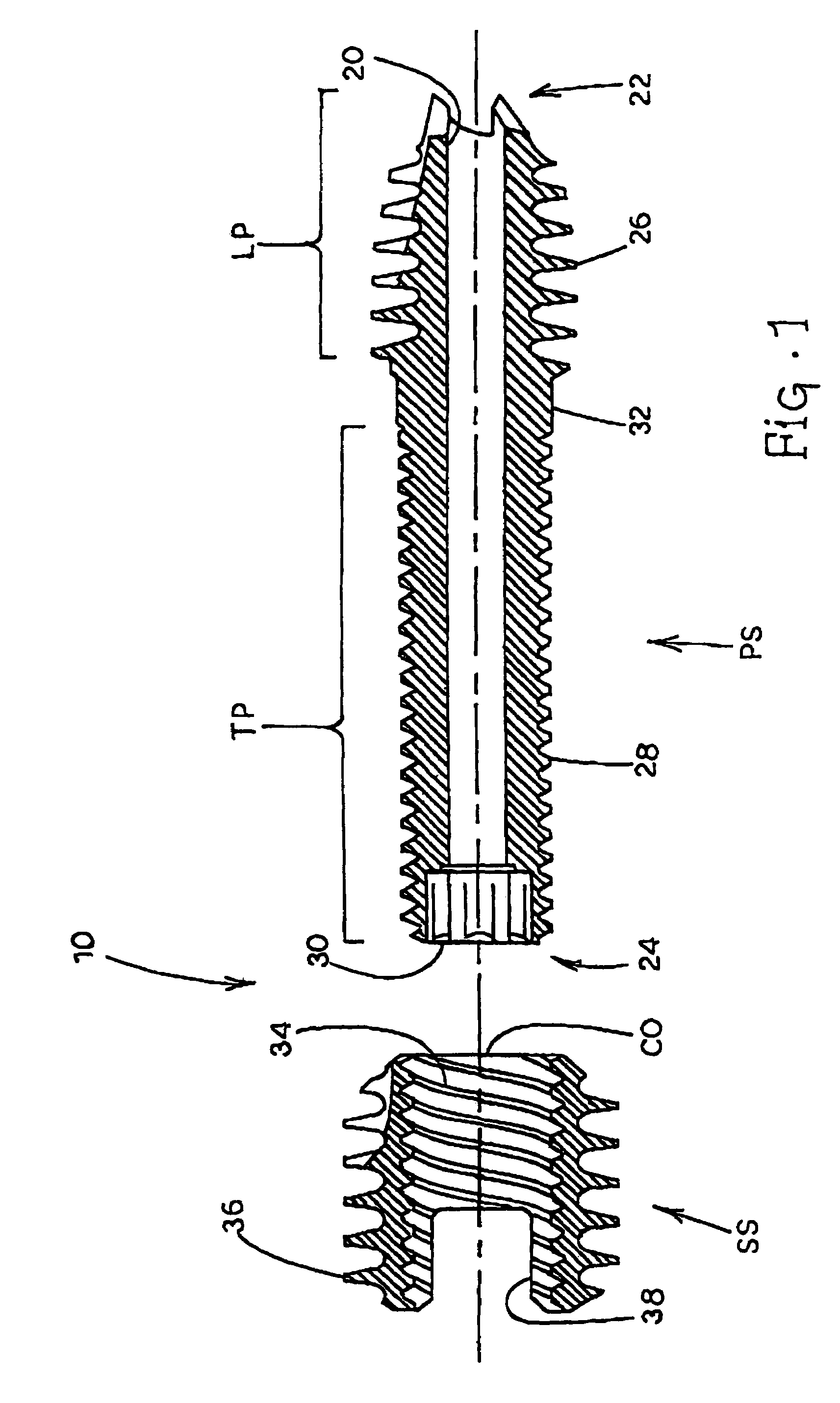
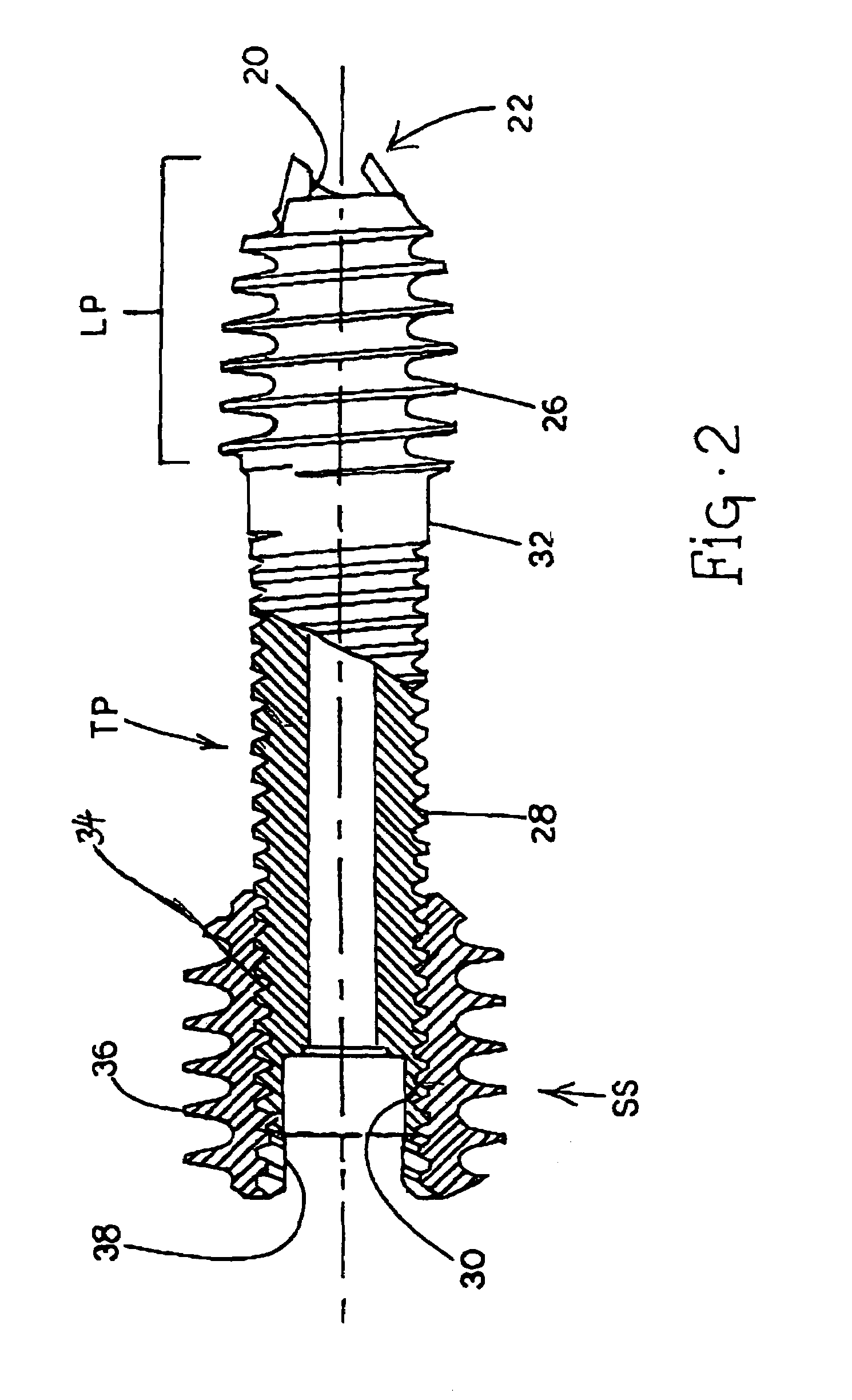
[0022]It is therefore an object to provide novel compression screw apparatuses, systems and methods which can easily and effectively be used to compress suitable materials, particularly for compression of bone fragments across a fracture line.

Problems solved by technology

Many complications typically exist, however, with this technique that prevent successful or optimal outcomes in all cases.
Treatment methods can also significantly impact healing time, pain, and functional outcomes.
Moreover, the necessity of reducing operative time is driven both by patient risk of infection, anesthetic complications, and health care costs.
The pitch of the screw decreases between the leading and trailing ends thus causing the bone fragments in a fracture to be drawn together when the screw is installed across the bone fragments.

Method used


Image

  • Compression screw apparatuses, systems and methods
  • Compression screw apparatuses, systems and methods
  • Compression screw apparatuses, systems and methods

Examples


Embodiment Construction

[0030]As used herein, the terms set forth below have the following, associated definitions as known to those of skill in the art of screw apparatuses:[0031]PITCH—The distance from one point on a screw thread to a corresponding point on the next thread, measured parallel to the long axis of the screw.[0032]PITCH DIAMETER—On a straight screw thread, the diameter of an imaginary cylinder where the width of the thread and the width of the space between threads is equal. On a tapered screw thread, the diameter, at a given distance from a reference plane perpendicular to the axis of a imaginary cone, the surface of which would pass through the threads at such point as to make equal the width of the threads and the width of the spaces cut by the surface of the cone.[0033]LEAD—The distance a screw thread advances on one rotational turn, measured parallel to the axis. On a single-thread screw the lead and the pitch are identical; on a double-thread screw the lead is twice the pitch; on a tri...


PUM


Abstract

Compression screw apparatuses, systems and methods are disclosed. In one embodiment, the compression screw includes a primary screw and a secondary screw. The primary screw includes an at least partially threaded leading portion and an at least partially threaded trailing portion. The secondary screw includes outer threads and has a central opening which is also threaded and adapted for being screwed onto and matingly engaging the trailing portion of the primary screw. Drivers can be used to rotatably control the primary screw and the secondary screw to cause compression of spaced-apart material, particularly for compression of bone fragments across a fracture line.

Description

RELATED APPLICATIONS[0001]This application claims the benefit of U.S. Provisional Patent Application Ser. No. 60 / 444,565, filed Feb. 3, 2003, the disclosure of which is incorporated herein by reference in its entirety.TECHNICAL FIELD[0002]The subject matter disclosed herein relates generally to screw apparatuses and methods. More particularly, the present subject matter relates to screw apparatuses, systems and methods adapted for compression of suitable materials, particularly for compression of bone fragments across a fracture line or lines.RELATED ART[0003]A variety of screw apparatuses and methods have been developed for use in compression of various materials, particularly in the fields of orthopedics, podiatry, and chiropody. The prior art includes various types of screws for placement into bone for compressing bone fragments across a fracture line. As such, it is well known to utilize a screw for placement across a fracture or osteotomy in order to compress, or as is referred...

Claims


Application Information

Patent Timeline
IPC IPC(8): A61B17/86A61BA61B17/16A61B17/56A61B17/58
CPCA61B17/863A61B17/8685A61B17/8635A61B17/1615A61B17/864A61B17/8645Y10S606/916
Inventor TRAIL, IAN A.WEISS, ARNOLD-PETER C.REINDEL, ERIC S.
Owner INTEGRA LIFESCI
Learn More