Modular hemostatic valve
a technology of hemostatic valve and module, which is applied in the field of medical devices, can solve the problems of leaving the indwelling device undisturbed, and achieve the effect of preventing slippag
- Summary
- Abstract
- Description
- Claims
- Application Information
AI Technical Summary
Benefits of technology
Problems solved by technology
Method used
Image
Examples
first embodiment
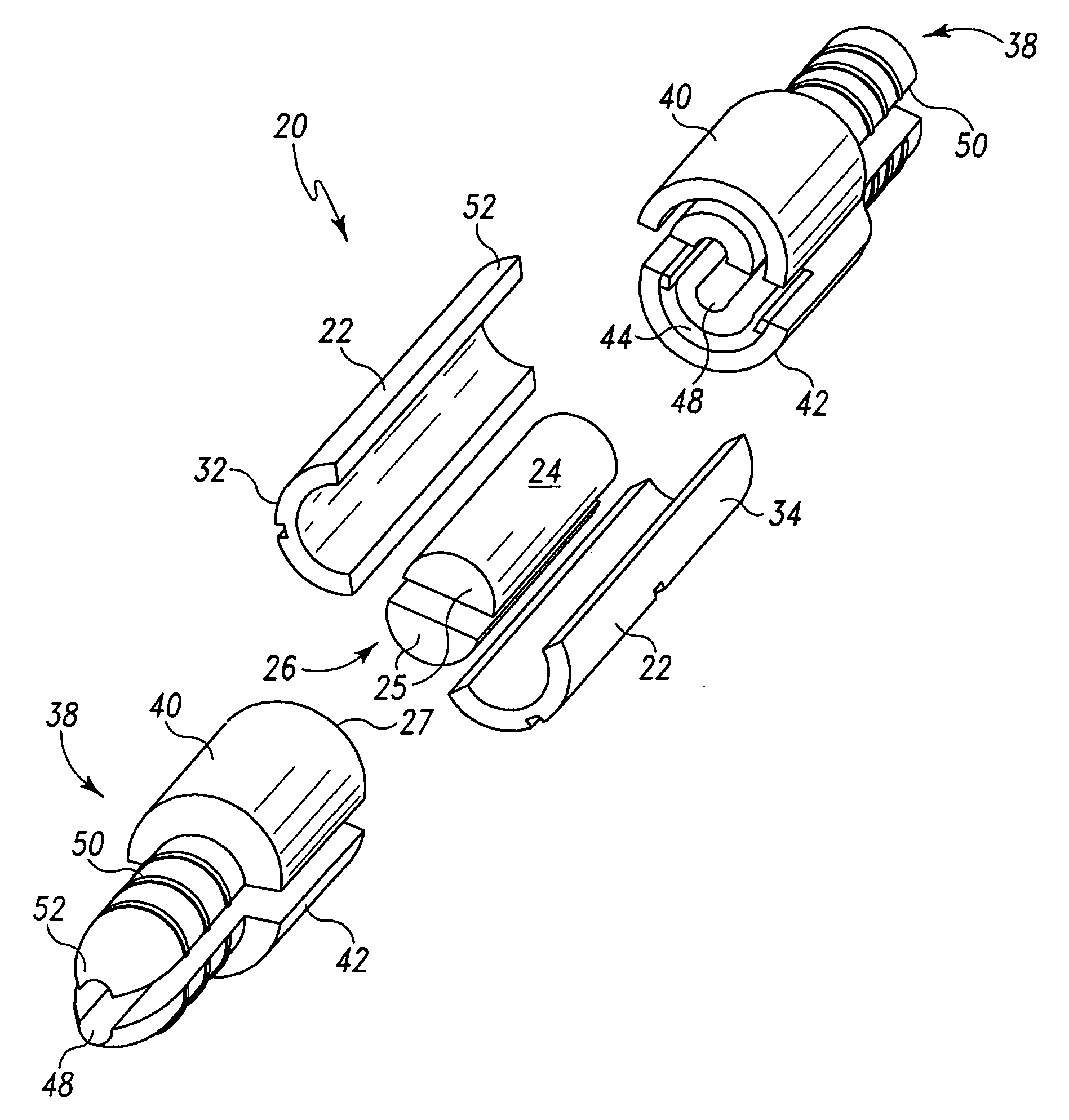
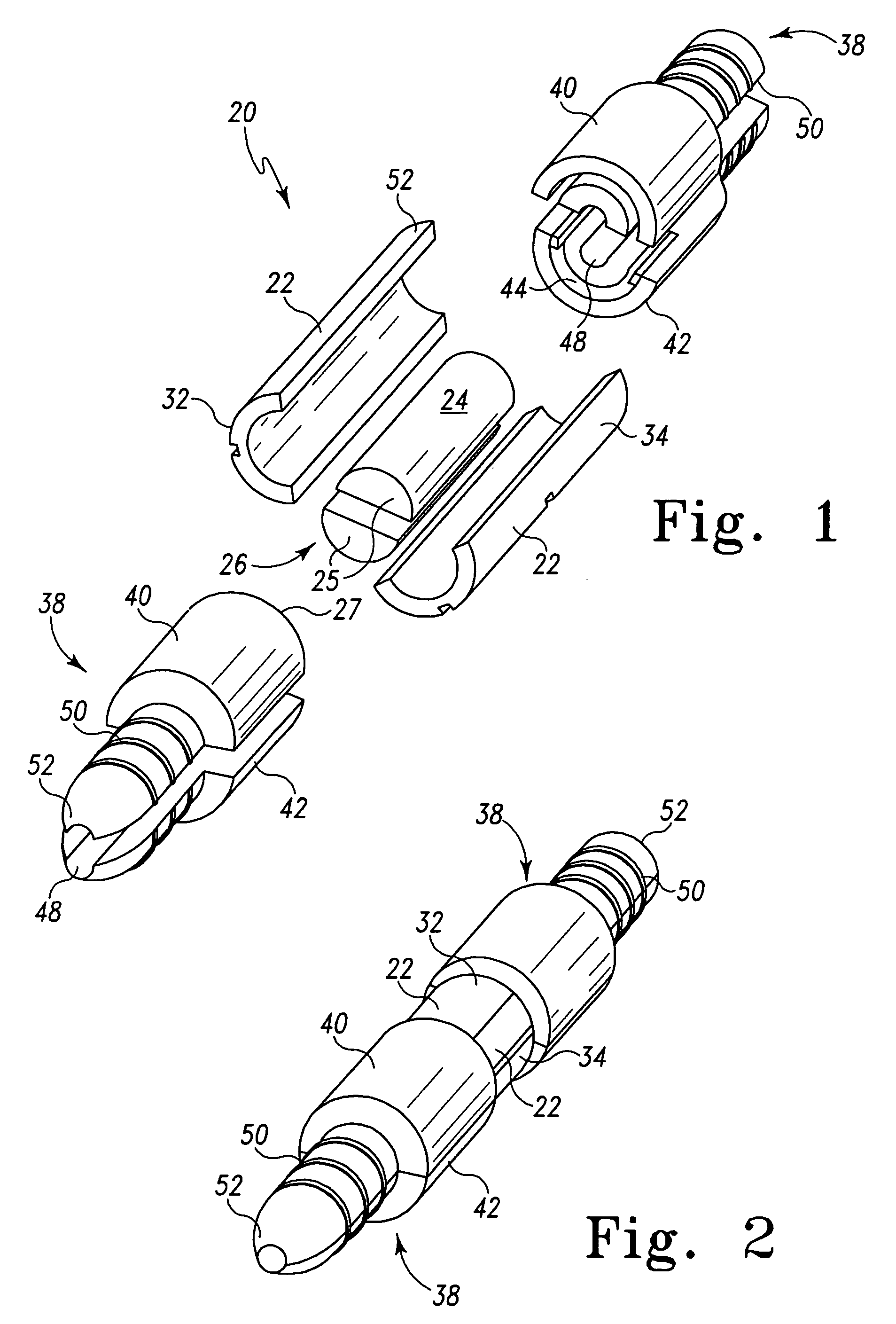
[0044]a modular hemostatic valve 20 of the present invention is shown in FIGS. 1 and 2 to include a splittable valve body 22 and a sealing element 24. The splittable valve body 22 defines a passageway 26, which is configured to house the sealing element 24. The sealing element 24 is configured to facilitate the passage of a first medical device, and the splittable valve body 22 is configured to engage a second medical device. The first medical device can be typically a catheter, dilator, or pacemaker lead, while the second medical device can be typically a tubular medical conduit such as a splittable introducer sheath.
[0045]The modular hemostatic valve 20 can substantially prevent or eliminate the leakage or flashback of blood or other bodily fluids. It should be noted that the modular hemostatic valve 20 has possible applications in other types of non-vascular procedures where there is a desire to prevent leakage of fluids and / or reduce exposure to air-borne pathogenic organisms. F...
second embodiment
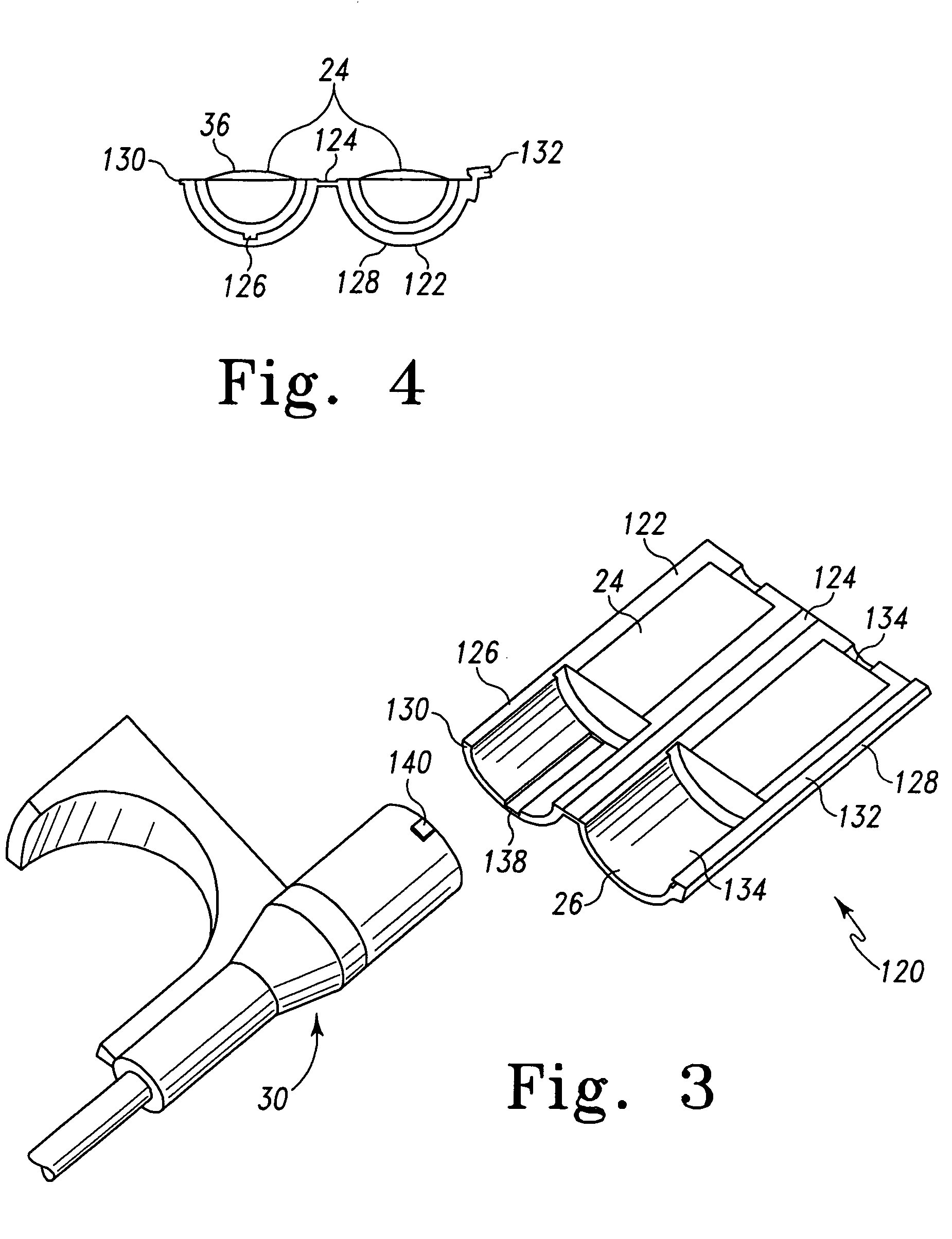
[0052]In a second embodiment, as depicted in FIGS. 3 and 4, the modular hemostatic valve 120 includes a splittable valve body 122 and the sealing element 24. The spliftable valve body 122 defines the passageway 26 and is configured to house the sealing element 24. The sealing element 24 is configured to facilitate the passage of the first medical device (not shown), as noted before, and the splittable valve body 122 is configured to engage a second medical device 30.
[0053]In this embodiment, the splittable valve body 122 includes a living hinge 124 attaching the first shell 126 and the second shell 128. The first shell 126 also includes an elongated protrusion 130, and the second shell 128 further includes a coupling hub 132 for capturing the elongated protrusion 130. In the preferred embodiment, the splittable valve body 122 includes a small aperture 134 to facilitate smooth passage of a relatively large-diameter first medical device 28 therethrough. Also in this embodiment, the se...
third embodiment
[0056]In a third embodiment, as depicted in FIGS. 10-14, the modular hemostatic valve assembly 220 includes a splittable valve body 222 with the passageway 26, and a sealing element 24 configured to traverse the passageway 26, similar to that shown in FIGS. 3-6. The splittable valve body 222 includes an interfacing region 224 to capture the second medical device 30. The splittable valve body 222 also includes a side port 226 that communicates with the passageway 26. The side port 226 can be used for a variety of purposes, for example, slow-drip intravenous administration. A length of tubing 228 can be attached to the side port 226 that, in turn, can include a luer lock port or similar-type fitting 230 to connect with a stop cock valve 232 or an I.V. line at the end distal to the patient. The side port 226 would be available to perform other functions such as infusion of medicaments, saline for flushing, or contrast media. The side port 226 could also be used to evacuate air from the...
PUM
 Abstract
Description
Claims
Application Information
 - R&D Engineer
- R&D Manager
- IP Professional
- Industry Leading Data Capabilities
- Powerful AI technology
- Patent DNA Extraction
Browse by: Latest US Patents, China's latest patents, Technical Efficacy Thesaurus, Application Domain, Technology Topic, Popular Technical Reports.
© 2024 PatSnap. All rights reserved.Legal|Privacy policy|Modern Slavery Act Transparency Statement|Sitemap|About US| Contact US: help@patsnap.com


