
Sample introduction and transfer system and method

a transfer system and sample technology, applied in the field of material handling systems and methods, can solve the problems of large load lock volume, large pumping time, and large cost of such a system, and achieve the effects of reducing the number of components, reducing cost, and simplifying the system

Inactive Publication Date: 2009-09-01
ULVAC PHI INC
View PDF25 Cites 11 Cited by
  • Summary
  • Abstract
  • Description
  • Claims
  • Application Information

AI Technical Summary

Benefits of technology

"The present invention provides a sample manipulator that can transfer and position samples for processing in a way that is simple, cost-effective, and versatile. The sample manipulator can perform both the transfer and positioning functions, eliminating the need for separate devices. This reduces the number of components, simplifies the process, and increases efficiency. The sample manipulator can also speed up the sample introduction process by reducing the volume of the high pressure zone in the load lock. Additionally, the invention provides a sealed barrier between the process chamber and the load lock chamber, allowing for the use of common hardware for processing and auxiliary functions. The system also includes a sample receiving stage, a load lock chamber, and a sample positioning apparatus that can move the sample receiving stage between an introduction position and a processing position. The load lock chamber can be opened and a sample removed for another sample to be positioned on the receiving stage. The system also includes an auxiliary seal mechanism and a manipulator mechanism that can move the sample receiving stage along at least two axes."

Problems solved by technology

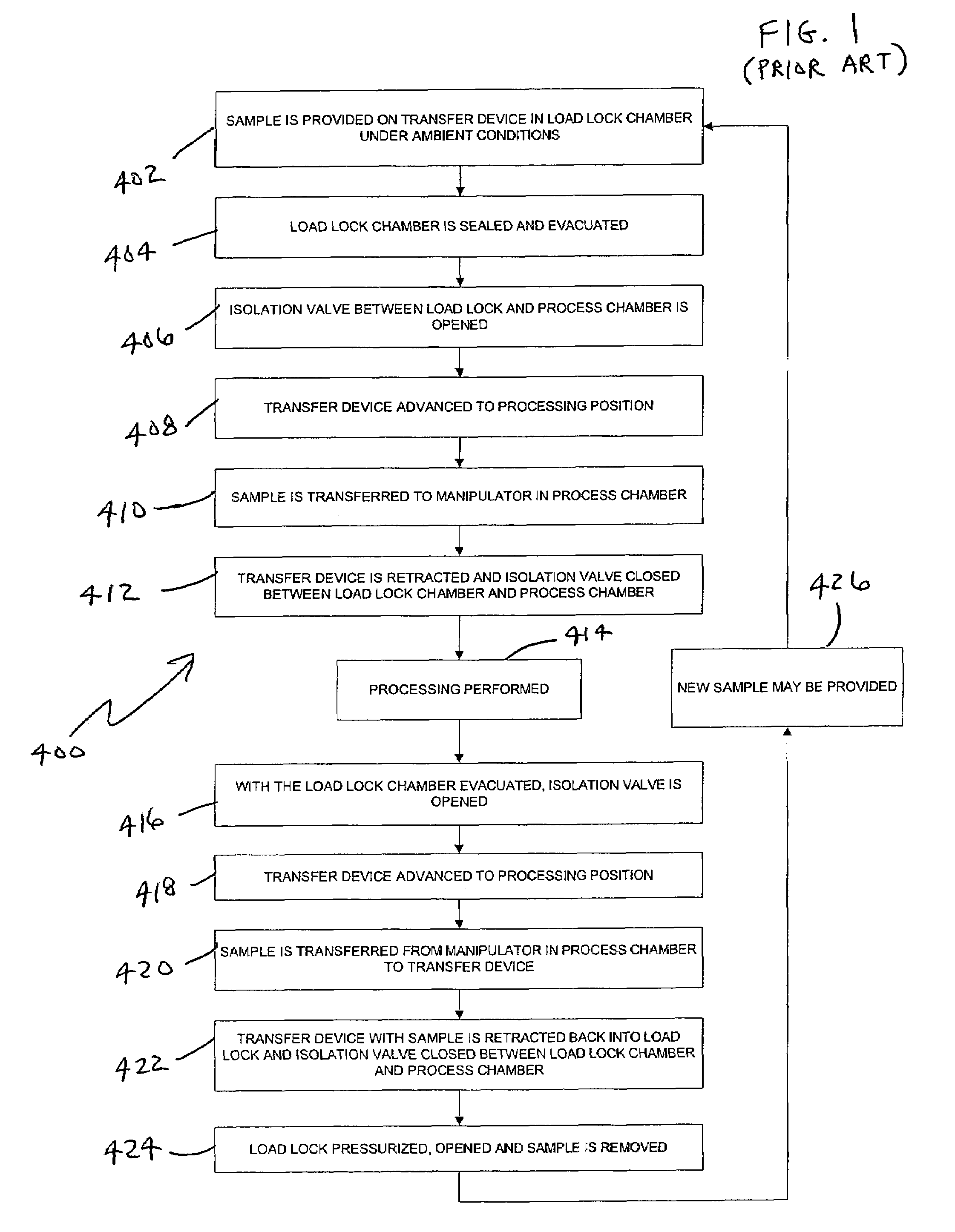
For example, a separate transfer apparatus and isolation valve are required components of the loading system and add significant cost to such a system.
Such a large pumping time decreases the speed of sample introduction.
Load lock volume is large requiring a longer time to achieve pressure equalization.
In other words, overall, loading reliability is undesirably low.
Clamping mechanisms have low rigidity to prevent sample vibration and low transfer position repeatability.
Yet further, conventional systems are fairly large in size due to the number of components and type of components used therein.
Overall system vibration is much greater because of the use of the transfer probe and such other additional components necessary for carrying out the functionality of such a conventional loading system.

Method used


Image

  • Sample introduction and transfer system and method
  • Sample introduction and transfer system and method
  • Sample introduction and transfer system and method

Examples


Embodiment Construction

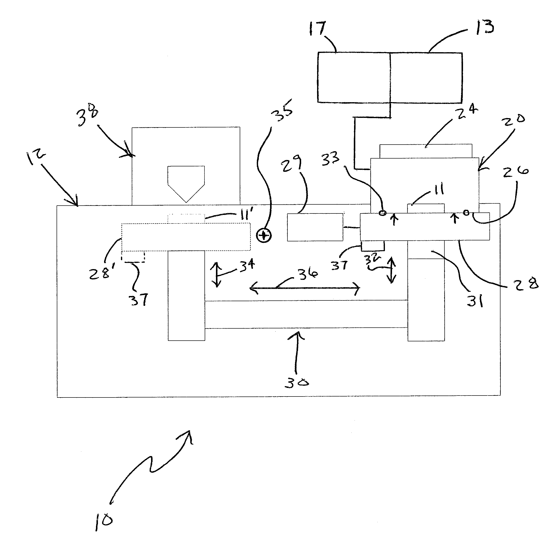
[0040]Generally, an introduction and process system 10 and a loading and processing method 50 shall be described with reference to FIGS. 3 and 4. Various illustrative embodiments of such systems and methods shall then be further described in more detail with reference to FIGS. 5 and 6A-6D.

[0041]One skilled in the art will recognize from the description herein, that various illustrative embodiments described include some features or elements included in other illustrative embodiments and / or exclude other features or elements. However, an introduction and process system, or a loading and processing method, according to the present invention, may include any combination of features or elements selected from one or more of the various embodiments, as described herein with reference to FIGS. 3-6. For example, one or more embodiments may include an optional auxiliary seal plate for sealing the load lock chamber when the sample is provided in the processing position (e.g., analysis positio...


PUM


Abstract

A method and system that provides a processing chamber associated with a load lock chamber. A sample receiving stage coupled to a sample positioning apparatus is configured to move between an introduction position and a processing analysis position within the process chamber. The sample receiving stage is used to result in a sealed barrier between the process chamber and the associated load lock chamber when in the introduction position.

Description

BACKGROUND OF THE INVENTION[0001]The present invention relates generally to material handling systems and methods. More particularly, the present invention pertains to sample handling methods and systems, such as, for example, those associated with processing systems (e.g., analysis systems such as systems designed to make surface measurements of samples, systems for performing deposition processes, etc.).[0002]Various loading systems are available for providing a sample into a process chamber (e.g., a process chamber held at below or above atmospheric pressure), such that the sample introduced into the process chamber can be analyzed by an instrument, any other process can be carried out with respect to the sample using one or more other process tools. For example, such analysis instruments may include scanning electron microscopes (SEMs), instruments for performing elipsometry, instruments for performing transmission electron microscopy (TEM), instruments for performing scanning t...

Claims


Application Information

Patent Timeline
Patent Type & Authority Patents(United States)
IPC IPC(8): H01L21/677
CPCB82Y35/00H01J37/20H01J37/185
Inventor MILLER, MARK C.
Owner ULVAC PHI INC
Learn More