
Laptop computer bin assembly for a worksurface

a technology for worksurfaces and computers, applied in convertible furniture, instruments, cabinets, etc., can solve the problems of reducing the size of computers, requiring a relatively complex construction of each table or desk, and occupying significant space on a desk or table top when being used, so as to reduce the overall cost and time. , the effect of simple construction

Inactive Publication Date: 2009-08-25
KRUEGER INT INC
View PDF28 Cites 40 Cited by
  • Summary
  • Abstract
  • Description
  • Claims
  • Application Information

AI Technical Summary

Benefits of technology

The present invention is a bin assembly for selectively displaying and storing items, such as a laptop computer, from a work surface. The assembly includes a base and an elevating mechanism for lifting and lowering a platform for holding the computer. A cover is pivotally secured to the enclosure for containing the computer when the platform is in the retracted position. The cover can be opened and closed to secure the computer in the enclosure. The cover also includes a latch and a lock mechanism to secure the computer in the enclosure. The bin assembly can be easily installed in a new or retrofit manner and has a simple construction to reduce costs and time.

Problems solved by technology

While advancements in computer technology have resulted in a reduction in the size of computers, such devices still occupy significant space on a desk or table top when being used.
However, each of these tables or desks involves a relatively complex construction in order to accommodate the particular elevating mechanism and / or object retaining structure.
Therefore, the costs and time required for the production of such desks or tables is quite high.
Also, due to the significant number of components required, the maintenance and repair costs for such desks and tables are also significantly higher than the costs associated with conventional desks and tables that are used for supporting computers.

Method used


Image

  • Laptop computer bin assembly for a worksurface
  • Laptop computer bin assembly for a worksurface
  • Laptop computer bin assembly for a worksurface

Examples


Embodiment Construction

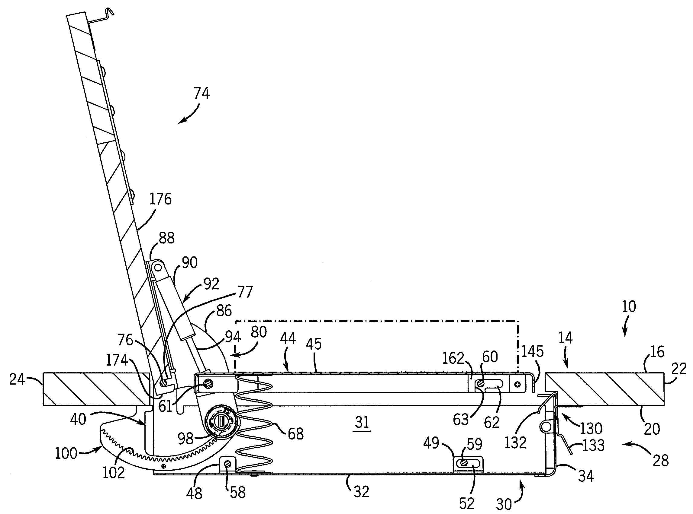
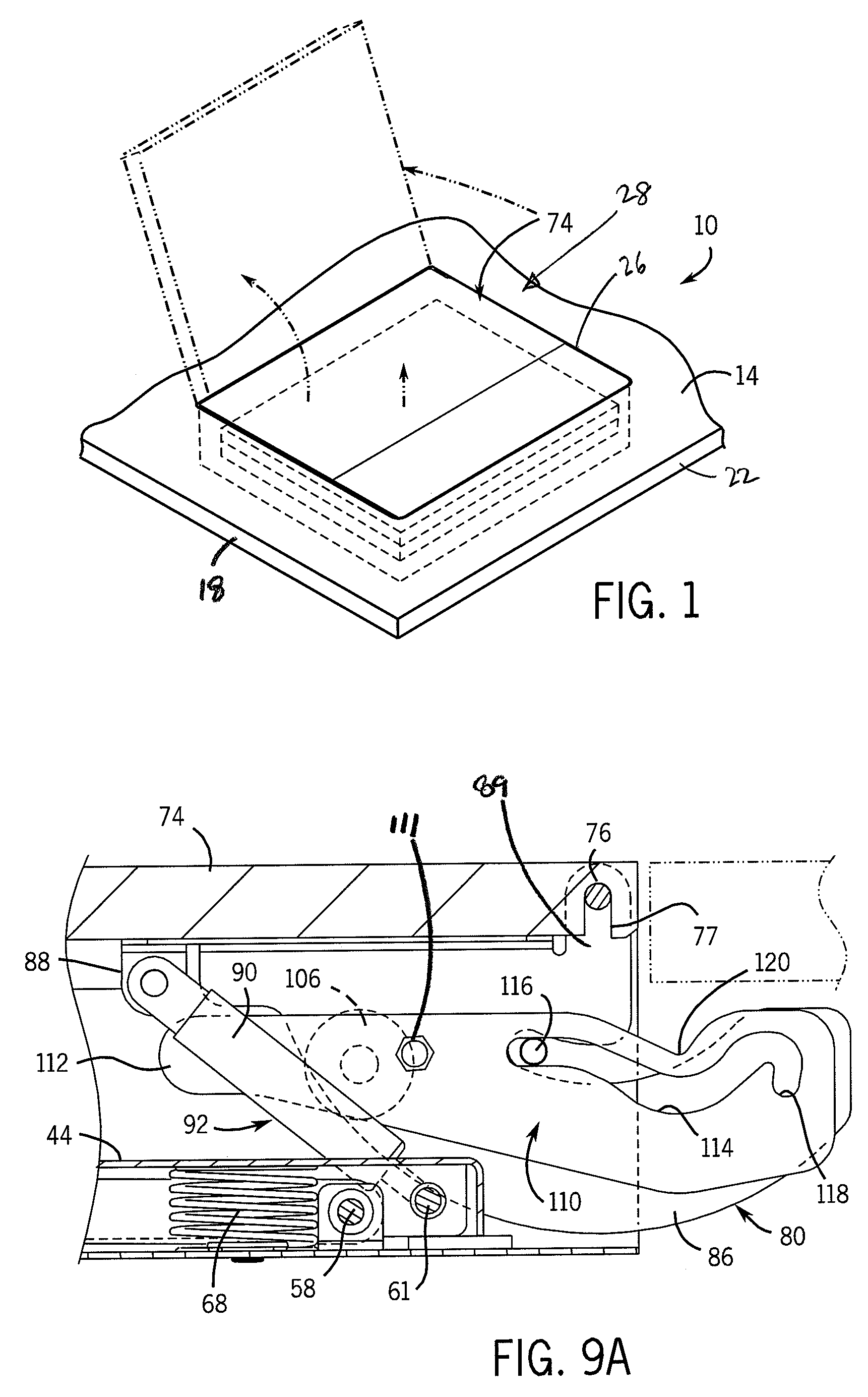
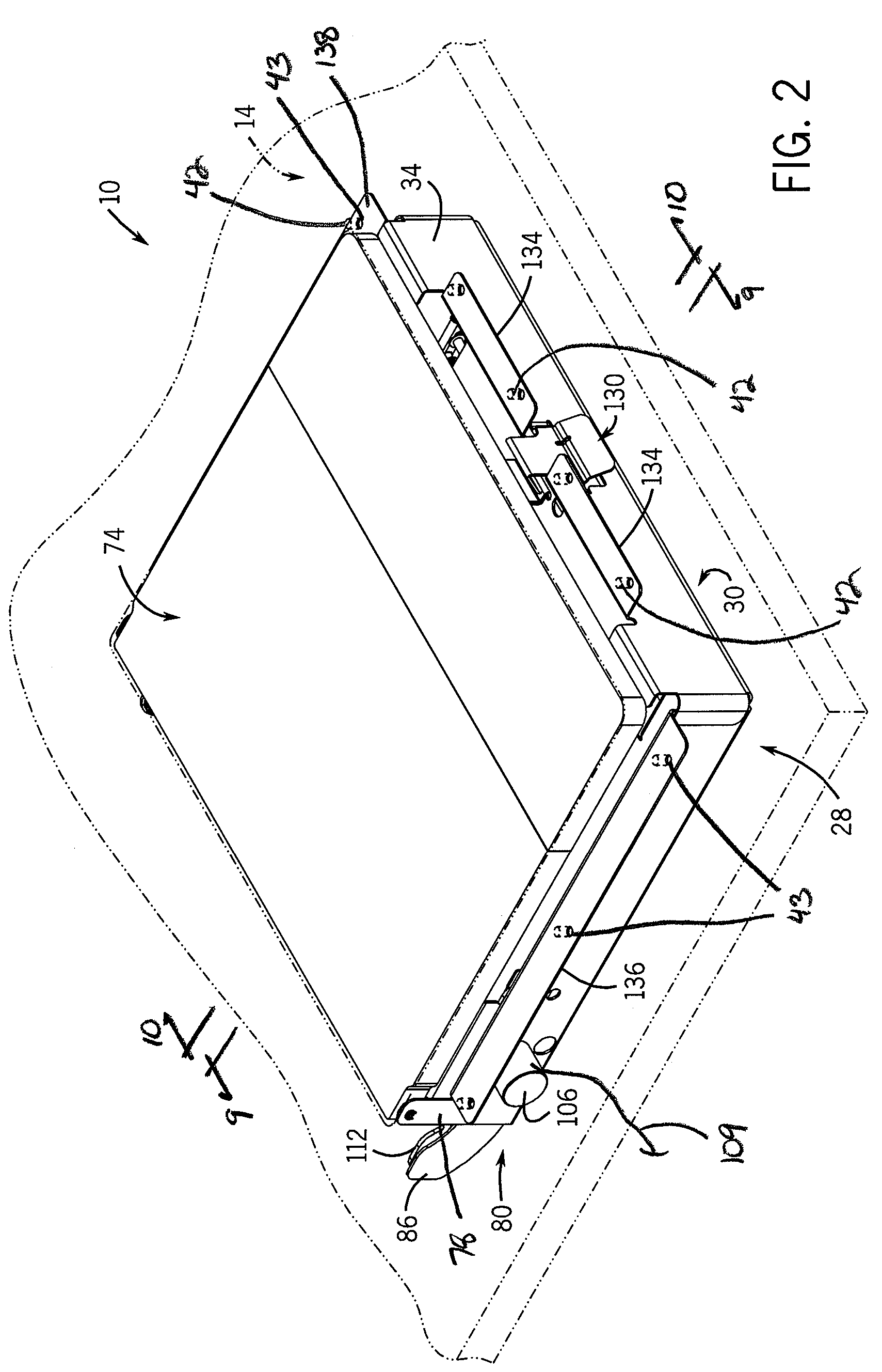
[0029]With reference now to the drawing figures in which like reference numerals designate like parts throughout the disclosure, a bin assembly constructed according to the present invention is indicated generally at 28 in FIGS. 1-10. The bin assembly 28 includes an enclosure 30 formed of a generally rigid material, such as a metal or hard plastic, and having an open interior 31, a bottom wall 32, a front wall 34 joined to the bottom wall 32, and a pair of side walls 36, 38 joined to the bottom wall 32 and each extending rearwardly from the front wall 34. The enclosure 30 can be formed in any satisfactory manner such that each of the respective walls 32-38 are connected with one another. Representatively, the bottom wall 32 and the side walls 36 and 38 may be formed together, and the front wall 34 may be formed separately and then assembled to bottom wall 32 and side walls 36, 38 to form the enclosure 30. In addition, the enclosure 30 defines an open rear end 40 opposite the front w...


PUM


Abstract

A bin assembly capable of being secured to a work surface such as a table top includes an enclosure secured to the work surface. A platform and an elevating mechanism, which is capable of moving the platform vertically, are contained within the enclosure. The assembly also includes a cover pivotally secured over the enclosure and connected to the elevating mechanism for selectively operating the elevating mechanism, to elevate and lower the platform within the enclosure simultaneously with the movement of the cover to retract and expose an item, such as a laptop computer, positioned on the platform. The cover can be locked in the closed position by a locking mechanism engaged between the cover and the enclosure to secure the item within the assembly. The cover can also be locked in the open position by a lock bracket releasably engaged with the cover in the open position to prevent inadvertent closing of the cover.

Description

CROSS-REFERENCE TO RELATED APPLICATIONS[0001]This application claims the benefit of U.S. Provisional Patent Application Ser. No. 60 / 669,042, filed Apr. 7, 2005, which is incorporated by reference herein in its entirety.FIELD OF THE INVENTION[0002]The present invention relates to work surfaces, and more specifically to a bin assembly for use with a work surface which is capable of selectively enclosing and exposing items, such as a computing device, from within the work surface.BACKGROUND OF THE INVENTION[0003]Tables, desks and work stations have been modified in their construction in order to more readily accommodate computing devices such as desktop and laptop computers. While advancements in computer technology have resulted in a reduction in the size of computers, such devices still occupy significant space on a desk or table top when being used. Oftentimes it is necessary to remove a computer from the desk or table top in order to enable an individual to effectively utilize the ...

Claims


Application Information

Patent Timeline
Patent Type & Authority Patents(United States)
IPC IPC(8): A47B81/00
CPCA47B21/0073G06F1/1628A47B2200/0008A47B2021/0076
Inventor GEVAERT, STEVEN C.
Owner KRUEGER INT INC
Learn More