
Display controller, electronic equipment and method for supplying image data

a technology of image data and display controller, which is applied in the direction of static indicating devices, instruments, cathode-ray tube indicators, etc., can solve the problems of reducing the performance of display controllers, affecting the performance of system performance including display controllers, and reducing the capacity of memory. , to achieve the effect of reducing the data transfer time, and preventing the image processing time from becoming long

Inactive Publication Date: 2009-08-18
SEIKO EPSON CORP
View PDF13 Cites 1 Cited by
  • Summary
  • Abstract
  • Description
  • Claims
  • Application Information

AI Technical Summary

Benefits of technology

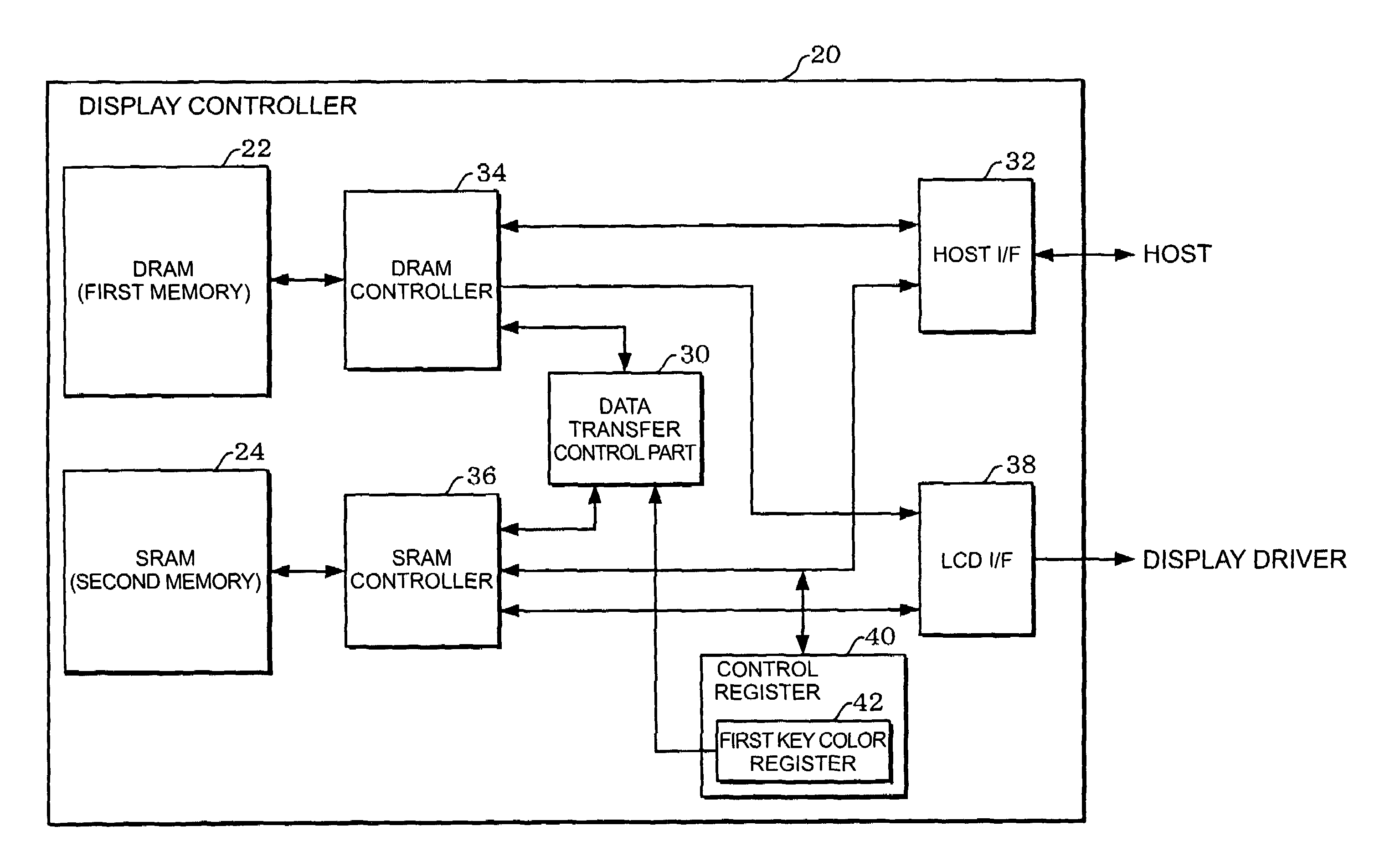
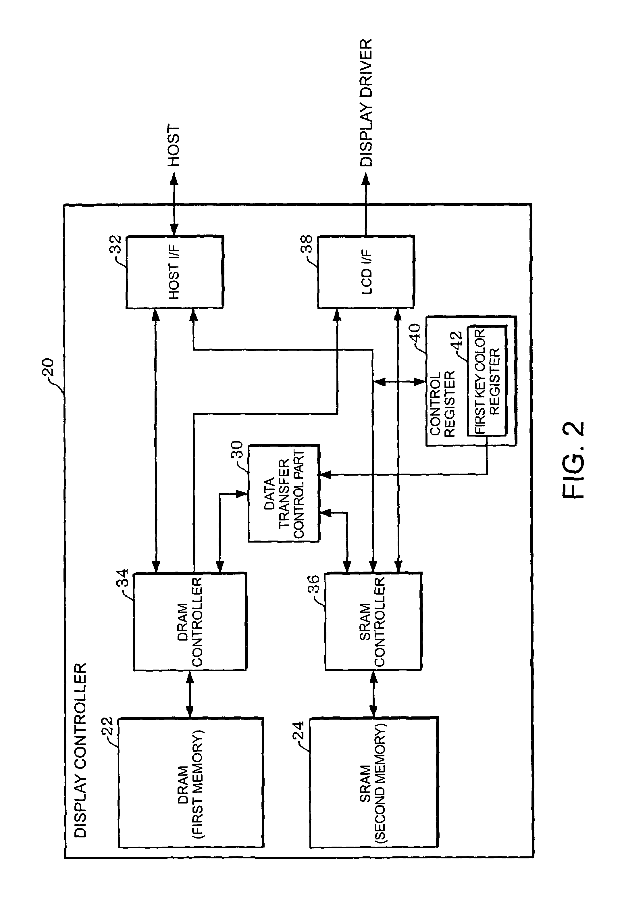
[0014]According to the first aspect of the invention, the image data stored in the first memory is once transferred to the second memory. The image processing is performed to the image data in the second memory and rewritten in the second memory, and then it is again written in the first memory. In this way, it can prevent that an image processing time becomes long which is caused by the long access time of the first memory at the time of random access and the long data transfer time. Accordingly, a processing load for controlling the display controller can be allotted to other process because the data transfer time is shortened. This can help a system performance including the display controller not to be lowered.
[0031]According to the second aspect of the invention, it is possible to provide electronic equipment which can prevent from the performance of the system and the image quality from being deteriorated.

Problems solved by technology

However, the small capacity of the memory was enough since a display size of the LCD panel was small.
Besides, a chip size of the display controller could be small.
Therefore, it takes a longer time to transfer the image data from the host to the memory housed in the display controller and from the display controller to the display driver.
In addition, a control for image data readout from the video memory becomes complicated.
Furthermore, the host cannot process other transaction during this data transfer process.
It leads to a low performance of the whole system.
A disadvantage in the packaging is pointed out when the capacity of the memory becomes larger and the chip size also gets larger.

Method used


Image

  • Display controller, electronic equipment and method for supplying image data
  • Display controller, electronic equipment and method for supplying image data
  • Display controller, electronic equipment and method for supplying image data

Examples


first modification example

[0146]2.1 First Modification Example

[0147]Though the data transfer control part 30 performs the key color process when the image data is transferred from the DRAM 22 to the SRAM 24 in the above-described embodiment, the present invention is not limited to this.

[0148]Besides when the image data is transferred from the DRAM 22 to the SRAM 24, the key color process is also performed when the image data is transferred from the SRAM 24 to the DRAM 22 in a first modification example of the invention.

[0149]FIG. 16 is a block diagram showing a configuration example of a data transfer control part 300 in the first modification example. The same structures as those of the data transfer control part 30 in the above-described embodiment shown in FIG. 12 are given the identical numerals and those explanations will be omitted.

[0150]In the data transfer control part 300 shown in FIG. 16, a comparator CMP2 and a mask circuit MSK2 are added to the data transfer control part 30 shown in FIG. 12. A se...


PUM


Abstract

The display controller includes a first memory storing image data and being accessed with a sequential access operation having a shorter access time than that of a random access operation, a second memory storing image data and consuming a less power than the first memory does at the time of the access operation and a data transfer control part performing an image data transfer control between the first memory and the second memory. The data transfer control part performs a transfer control to transfer the image data from the first memory to the second memory and transfer the image data written in the second memory after the image processing from the second memory to the first memory. The display controller supplies the image data in the first memory to a display driver.

Description

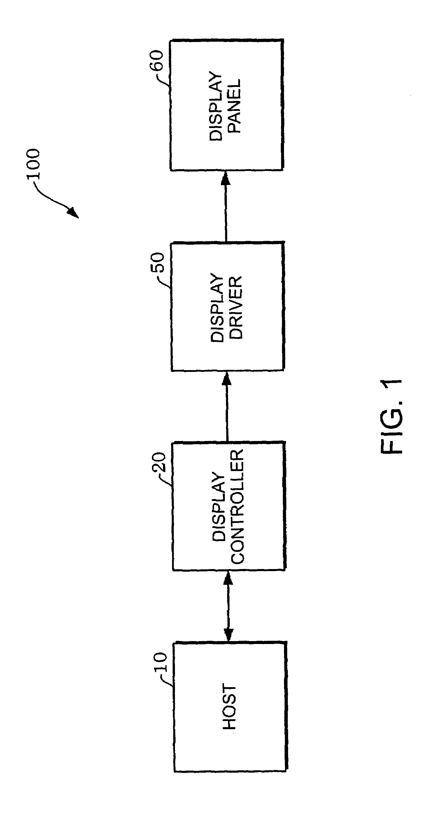
RELATED APPLICATIONS[0001]This application claims priority to Japanese Patent Application No. 2004-195607 filed Jul. 1, 2004 which is hereby expressly incorporated by reference herein in its entirety.BACKGROUND[0002]1. Technical Field[0003]The present invention relates to a display controller, electronic equipment and a method for supplying image data.[0004]2. Related Art[0005]Mobile devices (electronic equipment in a broad sense) such as a mobile phone often have display panels including a liquid crystal display (LCD) panel in recent years. A display panel is driven by a display driver based on image data. The image data is sometimes taken by a camera module and sometimes is generated or converted by a host. The display driver receives such image data and a display synchronizing signal and performs a driving control of the display panel.[0006]A display controller can take over the supply of the image data and the display synchronizing signal from the host. This means that the displ...

Claims


Application Information

Patent Timeline
Patent Type & Authority Patents(United States)
IPC IPC(8): G06F13/00G09G5/02G09G5/36
CPCG09G3/3611G09G5/393G09G5/363G09G5/02
Inventor OBINATA, ATSUSHI
Owner SEIKO EPSON CORP
Learn More