
System and method for automatic multiple listener room acoustic correction with low filter orders

a filter order and multi-listener technology, applied in the field of multi-channel audio, can solve the problems of affecting the equalization performance of the filter for a specific receiver (or listener), distorted frequency response of the audio signal at the receiving position, and poor equalization performance at other locations in the room

Active Publication Date: 2009-07-28
AUDYSSEY LABORATORIES
View PDF8 Cites 41 Cited by
  • Summary
  • Abstract
  • Description
  • Claims
  • Application Information

AI Technical Summary

Benefits of technology

The present invention provides a system and method for delivering distortion-free audio to multiple listeners in various environments. The system includes a room acoustic correction filter that automatically corrects the room acoustical characteristics at multiple listener positions. The filter is designed to provide a flat magnitude response in the frequency domain and a signal that resembles an impulse function in the time domain at each expected listener position. The method involves measuring the acoustical characteristics of the environment at each expected listener position and using a pattern recognition method to determine the filter. The filter can be the inverse of the minimum-phase signal or a filtered version of the minimum-phase signal. The technical effect of the invention is to provide high-quality audio to multiple listeners in any environment, resulting in improved sound quality and reduced distortion.

Problems solved by technology

Now, when sound is transmitted in a room from a source to a specific receiver, the frequency response of the audio signal is distorted at the receiving position mainly due to interactions with room boundaries and the buildup of standing waves at low frequencies.
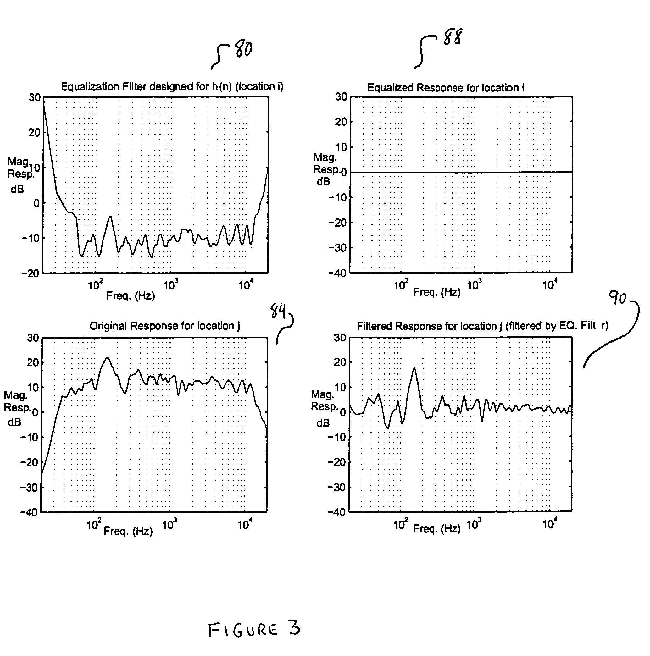
However, the inventors have realized that at least two problems arise when using this approach, (i) the room response is not necessarily invertible (i.e., it is not minimum phase), and (ii) designing an equalizing filter for a specific receiver (or listener) will produce poor equalization performance at other locations in the room.
In other words, multiple-listener equalization cannot be achieved with a single equalizing filter.
Thus, room equalization, which has traditionally been approached as a classic inverse filter problem, will not work in practical environments where multiple-listeners are present.

Method used


Image

  • System and method for automatic multiple listener room acoustic correction with low filter orders
  • System and method for automatic multiple listener room acoustic correction with low filter orders
  • System and method for automatic multiple listener room acoustic correction with low filter orders

Examples


Embodiment Construction

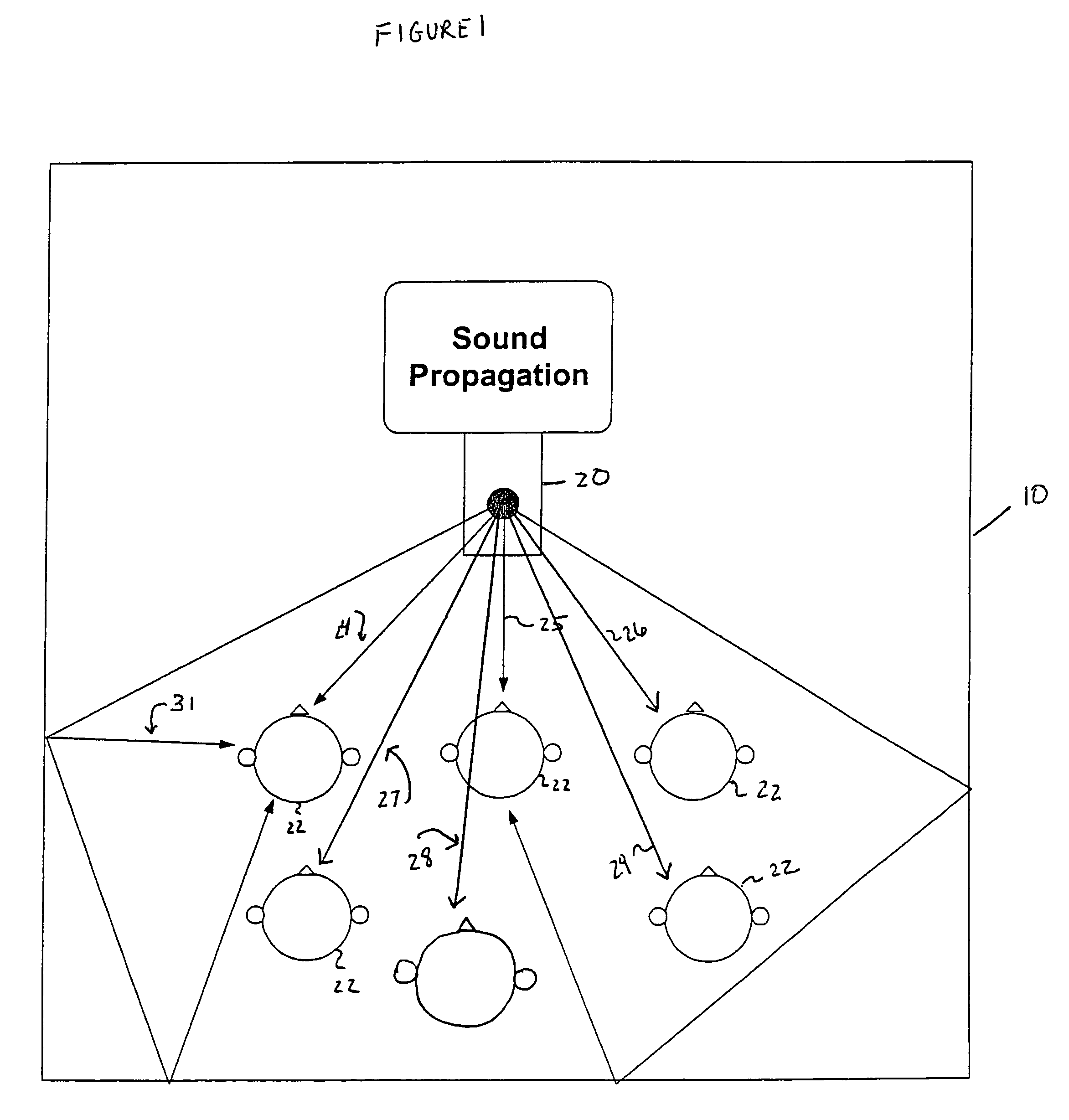
[0061]FIG. 1 shows the basics of sound propagation characteristics from a loudspeaker (shown as only one for ease in depiction) 20 to multiple listeners (shown to be six in an exemplary depiction) 22 in an environment 10. The direct path of the sound, which may be different for different listeners, is depicted as 24, 25, 26, 27, 28, 29, and 30 for listeners one through six. The reflected path of the sound, which again may be different for different listeners, is depicted as 31 and is shown only for one listener here (for ease in depiction).

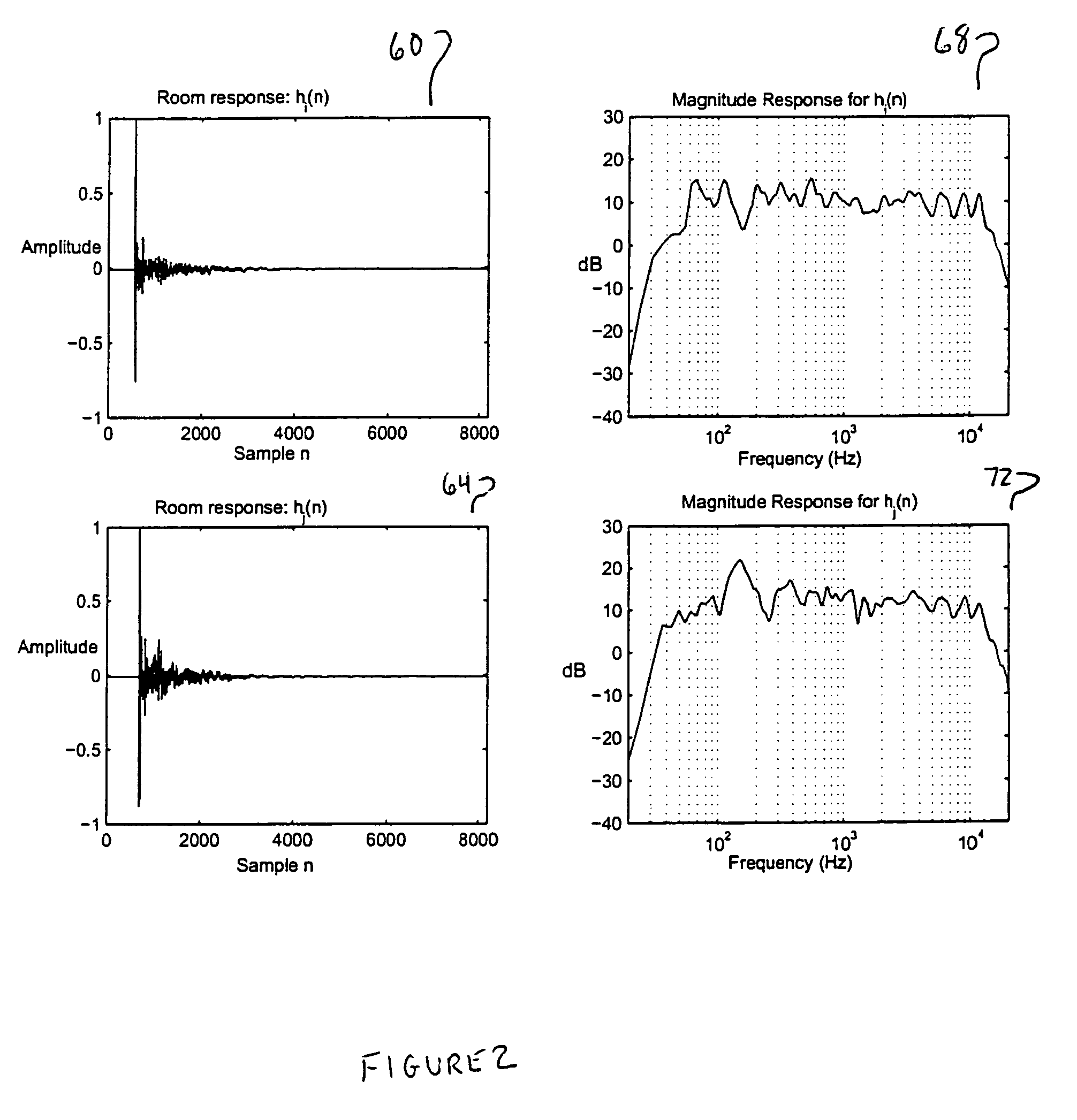
[0062]The sound propagation characteristics may be described by the room acoustical impulse response, which is a compact representation of how sound propagates in an environment (or enclosure). Thus, the room acoustical response includes the direct path and the reflection path components of the sound field. The room acoustical response may be measured by a microphone at an expected listener position. This is done by, (i) transmitting a stimulus si...


PUM


Abstract

A system and a method for correcting, simultaneously at multiple-listener positions, distortions introduced by the acoustical characteristics includes warping room responses, intelligently weighing the warped room acoustical responses to form a weighted response, a low order spectral fitting to the weighted response, forming a warped filter from the low order spectral fit, and unwarping the warped filter to form the room acoustical correction filter.

Description

CROSS-REFERENCE TO RELATED APPLICATIONS[0001]The present application is a continuation-in-part of and claims priority to U.S. application Ser. No. 10 / 465,644 filed Jun. 20, 2003 which claims the benefit of priority to U.S. Provisional Patent Application 60 / 390,122 filed Jun. 21, 2002, which are incorporated by reference in their entirety herein.BACKGROUND[0002]1. Field of the Invention[0003]The present invention relates to multi-channel audio and particularly to the delivery of high quality and distortion-free multi-channel audio in an enclosure.[0004]2. Description of the Background Art[0005]The inventors have recognized that the acoustics of an enclosure (e.g., room, automobile interior, movie theaters, etc.) play a major role in introducing distortions in the audio signal perceived by listeners.[0006]A typical room is an acoustic enclosure that can be modeled as a linear system whose behavior at a particular listening position is characterized by an impulse response, h(n) {n=0, 1...

Claims


Application Information

Patent Timeline
Patent Type & Authority Patents(United States)
IPC IPC(8): H04R5/00H03G3/00H04R5/02H04S7/00
CPCH04S7/30H04S2400/09
Inventor BHARITKAR, SUNILKYRIAKAKIS, CHRIS
Owner AUDYSSEY LABORATORIES
Learn More