
Lacrosse head

a technology of lacrosse head and catching head, which is applied in the field of lacrosse head, can solve the problems of increasing the possibility of users stringing their heads, reducing the effective catching area of the lacrosse head, and increasing the possibility of users catching their heads, so as to prevent the lacrosse ball from being dislodged from the head, increasing the area, and being stronger and lighter

Inactive Publication Date: 2009-07-21
WARRIOR SPORTS INC
View PDF31 Cites 18 Cited by
  • Summary
  • Abstract
  • Description
  • Claims
  • Application Information

AI Technical Summary

Benefits of technology

"The present invention provides a lacrosse head with a ball retaining area that has an increased area for holding the ball within the head. The head also has a narrow pocket to keep the ball in line with the centerline of the stick and assists in preventing the ball from being dislodged from the head during use. The head has a throat configuration that is stronger and lighter than prior lacrosse heads. Overall, the present invention provides an improved lacrosse head with improved ball retention and performance."

Problems solved by technology

While these ridges assisted in ball retention because they extend from the sidewalls into the pocket, they decreased the effective catching area of the lacrosse head.
This configuration does provide some ball retention attributes, it also decreases the catching area of the head.
While the sidewalls were closer together in the rear portion, these efforts to decrease the width therebetween has also increased the possibility of users stringing their heads such that the ball will be lodged in the head due to the decreased width in the rear portion.

Method used


Image

  • Lacrosse head
  • Lacrosse head
  • Lacrosse head

Examples


Embodiment Construction

[0024]In the following figures, the same reference numerals are used to identify the same components in the various views.

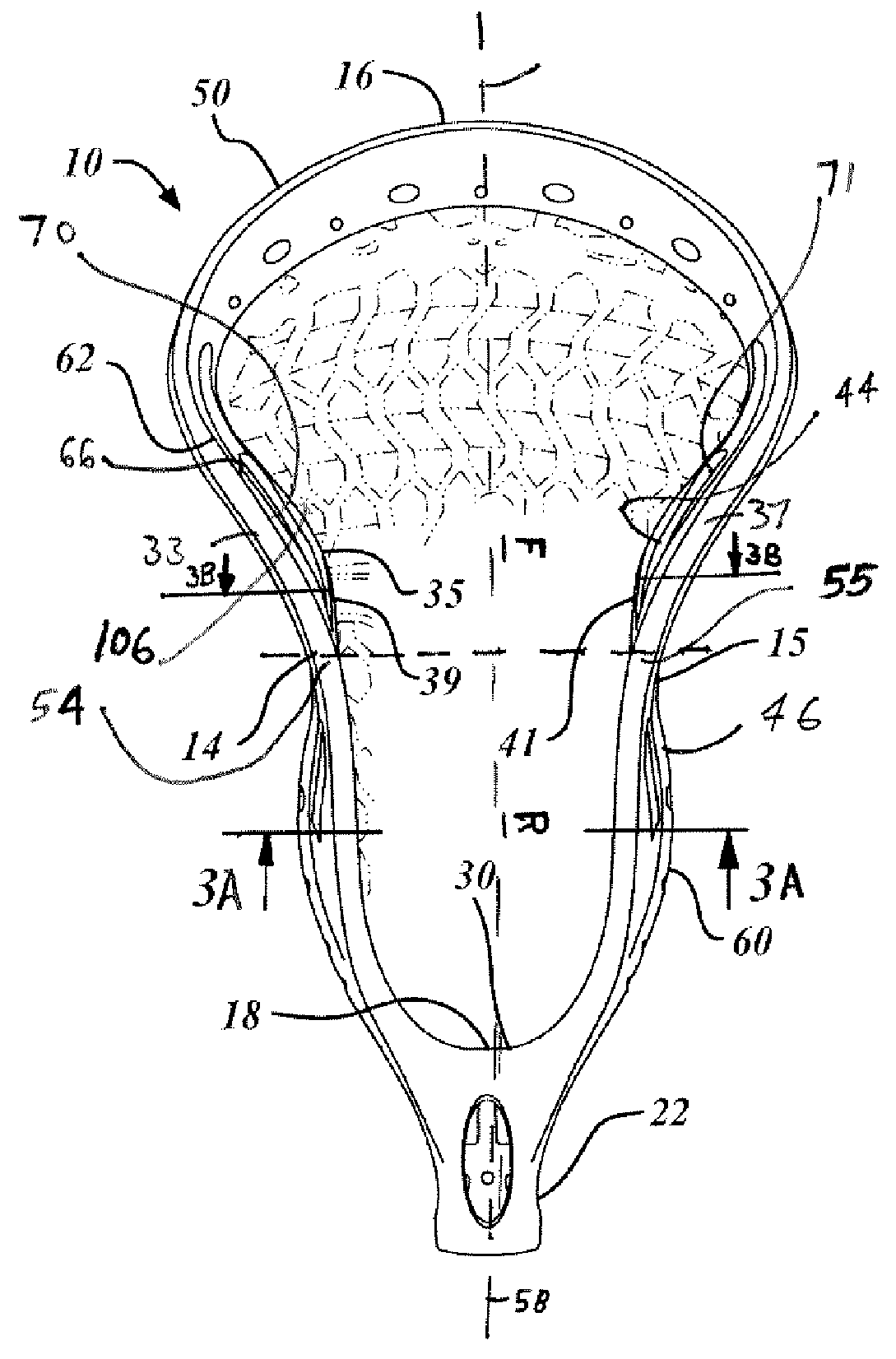
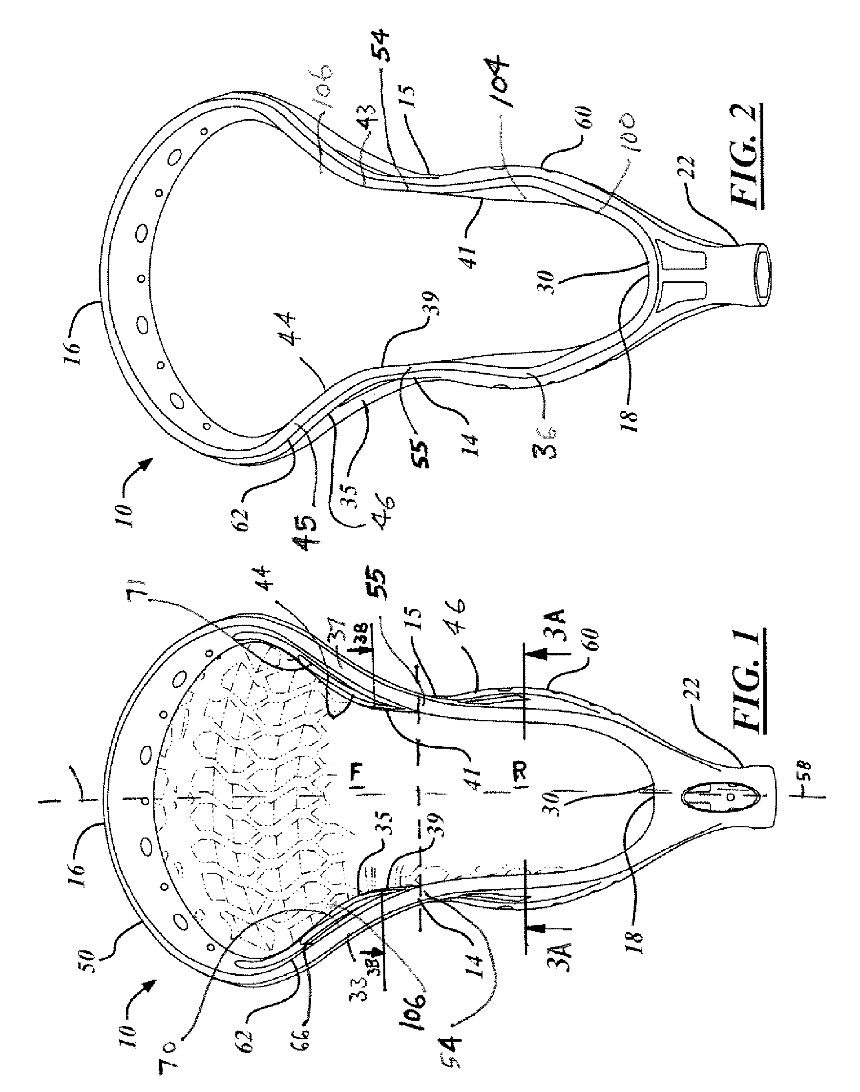
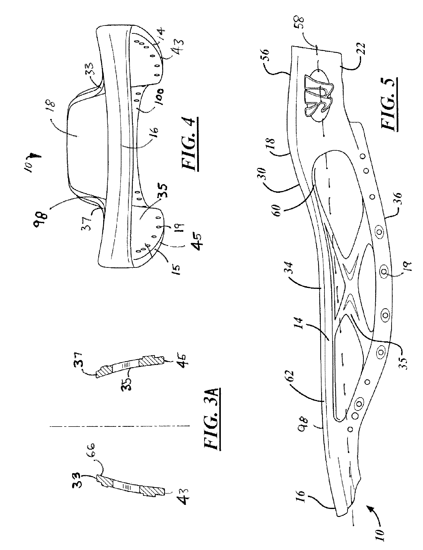
[0025]Referring to FIGS. 1 through 5, there are generally shown views of a lacrosse head 10 in accordance with one embodiment of the present invention. The lacrosse head 10 includes a pair of opposing sidewall portions 14, 15 or (left sidewall and right sidewall, respectively), a scoop portion 16 extending between and connecting the top ends of the sidewall portions 14, 15 and a base portion 18 extending between and connecting the bottom ends of the sidewall portions 14, 15. The lacrosse head 10 has a throat, socket or projection 22 that extends from the base portion 18 for attachment of a lacrosse stick handle therein. The attached handle defines a head / handle axis 58 along the centerline of the handle.

[0026]The pair of opposing sidewall portions 14, 15, the scoop portion 16, and the base portion 18 together form an open frame. In one embodiment, the frame is co...


PUM


Abstract

A lacrosse head includes a base, a scoop, and a pair of sidewalls. The sidewalls include upper and lower rims and further include a dual flare configuration. The first flare is in a rear portion and is characterized by the upper rims of the sidewalls being spaced closer together to one another than the lower rims. The second flare begins from approximately the middle portion of the sidewalls and generally throughout the forward portion and is characterized by the upper rims of the sidewalls being spaced further apart from each other than the lower rims.

Description

CROSS-REFERENCE TO RELATED APPLICATION[0001]The present application claims priority from U.S. Provisional Application Ser. No. 60 / 655,121, entitled “Dual Flared Lacrosse Head,” filed on Feb. 22, 2005, and U.S. Provisional Application Ser. No. 60 / 655,967, entitled “Dual Flared Lacrosse Head,” filed on Feb. 23, 2005, the disclosures of which are hereby incorporated by reference as though set forth fully herein.TECHNICAL FIELD[0002]The present invention relates generally to lacrosse heads, and more particularly to lacrosse heads having flared features for optimal playability.BACKGROUND OF THE INVENTION[0003]Lacrosse heads for use in the game of lacrosse are well-known and take on a variety of configurations. Current lacrosse heads are typically manufactured by injection molding processes and are secured to a metal lacrosse handle for use in play. The structure of lacrosse heads is commonly defined by a base portion disposed adjacent to a connection with the handle, a pair of opposing s...

Claims


Application Information

Patent Timeline
Patent Type & Authority Patents(United States)
IPC IPC(8): A63B59/02A63B65/12
CPCA63B59/02A63B59/20
Inventor MORROW, DAVIDWINNINGHAM, MATTHEW
Owner WARRIOR SPORTS INC
Learn More