
Delaying swelling in a downhole packer element

a technology of downhole packer and plug, which is applied in the direction of sealing/packing, fluid removal, borehole/well accessories, etc., can solve the problems of slowing down the process, and achieve the effect of slowing down the swelling rate and slowing down the process

Active Publication Date: 2009-07-21
BAKER HUGHES INC
View PDF34 Cites 33 Cited by
  • Summary
  • Abstract
  • Description
  • Claims
  • Application Information

AI Technical Summary

Benefits of technology

[0057]A swelling element rate regulation technique and product features an outer coating on a core of an element. The core is reactive to hydrocarbons or water depending on how it is configured. The surrounding coating is preferably formed of fine ground particles of a non-swelling polymer mixed in a solvent such as methyl-ethyl-ketone that is applied in a thin layer to the core exterior. This uncured outer layer is then contacted by a patterned surface. The patterned surface is pressed firmly against the uncured polymer / solvent mixture and transfers an inverse of the pattern to the surface of the coating. As pressure is applied, heat may also be applied to cure the coating. The resulting pattern is designed such that openings in the coating are created that regulate infiltration of water or other fluids through it and, as a result, the rate of swelling in the wellbore. Swell rate in governed in part by the ratio of the exposed area of the swelling compound to the total volume of the swelling compound. The smaller this ratio, the slower the rate of swell. The pattern created in the non-swelling layer may also provide limited mechanical restraint of the swelling element, further slowing the process.

Problems solved by technology

The pattern created in the non-swelling layer may also provide limited mechanical restraint of the swelling element, further slowing the process.

Method used


Image

  • Delaying swelling in a downhole packer element
  • Delaying swelling in a downhole packer element

Examples


Embodiment Construction

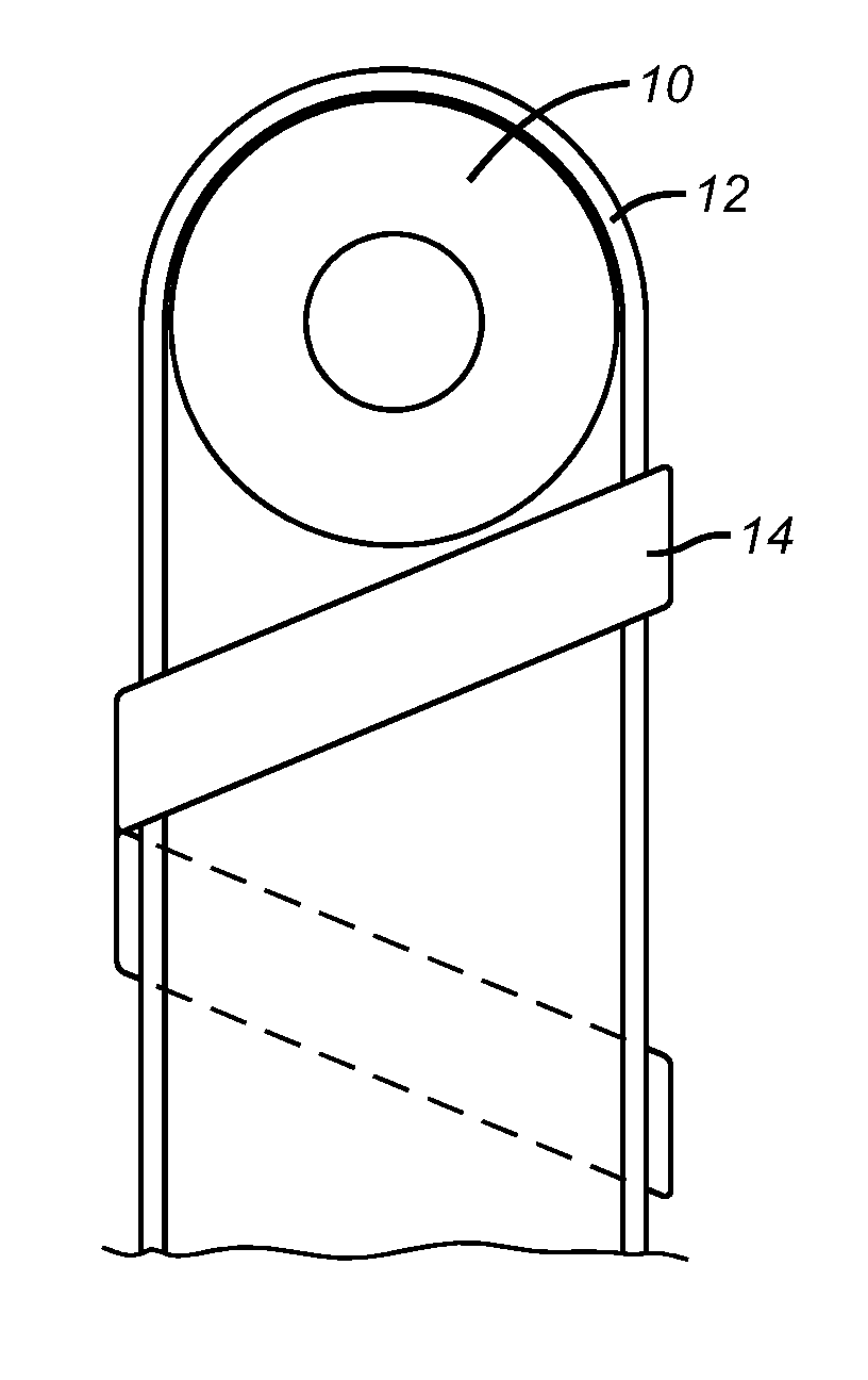
[0059]FIG. 1 shows a cylindrically shaped core 10 that can be configured to be water reactive or hydrocarbon reactive. In the preferred embodiment for a water reactive version, the bulk of the core 10 is a nitrile-based polymer with incorporated water absorbing particles. One example of such materials that absorb water is referred to as super absorbing particles or SAP. These particles absorb water and swell. The result is that the rubber swells without the water or SAP being absorbed into the rubber matrix which can adversely affect its abilities to act as a seal.

[0060]Alternatively, the core can be hydrocarbon reactive and made from an oleophillic polymer that absorbs hydrocarbons into its matrix. The swelling occurs from the absorption of the hydrocarbons which also lubricates and decreases the mechanical strength of the polymer chain as it expands. EPDM is one example of such a material.

[0061]The present inventions is an effective way to delay the swelling in either type of elem...


PUM


Abstract

A swelling element rate regulation technique and product features an outer coating on a core of an element. The core is reactive to hydrocarbons or water depending on how it is configured. The surrounding coating is preferably formed of fine ground particles of a non-swelling polymer mixed in a solvent such as methyl-ethyl-ketone that is applied in a thin layer to the core exterior. This uncured outer layer is then contacted by a patterned surface. The patterned surface is pressed firmly against the uncured polymer / solvent mixture and transfers an inverse of the pattern to the surface of the coating. As pressure is applied, heat may also be applied to cure the coating. The resulting pattern is designed such that openings in the coating are created that regulate infiltration of water or other fluids through it and, as a result, the rate of swelling in the wellbore. Swell rate in governed in part by the ratio of the exposed area of the swelling compound to the total volume of the swelling compound. The smaller this ratio, the slower the rate of swell. The pattern created in the non-swelling layer may also provide limited mechanical restraint of the swelling element, further slowing the process.

Description

FIELD OF THE INVENTION[0001]The field of this invention relates to downhole packers and plugs that use a swelling element and more particularly to design that delay the onset of swelling once the element is run downhole.BACKGROUND OF THE INVENTION[0002]Packers are used downhole to isolate portions of a wellbore from each other. There are many styles of packers. Some set by longitudinal compression of the sealing element by fluid pressure applied to a setting tool or by mechanical force such as from setting down weight. Other designs involve elements that are inflated. More recently, elements that swell to a sealing position on exposure to well fluids have been used. There have been many variations as outlined below.[0003]Packers have been used that employ elements that respond to the surrounding well fluids and swell to form a seal. Many different materials have been disclosed as capable of having this feature and some designs have gone further to prevent swelling until the packer i...

Claims


Application Information

Patent Timeline
IPC IPC(8): E21B33/12
CPCE21B33/1277E21B33/1208
Inventor WOOD, EDWARD T.O'MALLEY, EDWARD J.
Owner BAKER HUGHES INC
Learn More