
Total home energy management system

a technology for managing systems and homes, applied in the field of total home energy management systems, can solve problems such as the obvious opportunity to facilitate residential energy management, and achieve the effects of selective supply or curtailment of power to the appliance, increased electronic sensing and control of the functionality of the appliance, and increased data exchange capability

Inactive Publication Date: 2009-07-14
WHIRLPOOL CORP
View PDF81 Cites 224 Cited by
  • Summary
  • Abstract
  • Description
  • Claims
  • Application Information

AI Technical Summary

Benefits of technology

[0010]Recent trends in appliances include more electronic sensing and control of appliance functionality as well as an increased capability to exchange data between an appliance and computers and other devices external of the appliance. As a result of the trend towards electronic control, many methods and devices are well known to remotely communicate with appliances to sense, monitor and control them. Many methods and devices are also known to provide devices, such as smart modules built into electrical sockets or disposed along the power distribution system to an appliance or other energy consuming device, to selectively supply or curtail power to that appliance or device. Such devices and methods may include means for detecting whether an appliance is operating and even for determining what type of appliance or device is drawing power and gathering diagnostic information from the appliance or device. This presents an unobvious opportunity to facilitate residential energy management.
[0011]In light of the above noted problems, the invention provides a system that distributes the primary decision making ability over energy savings to a home owner. When implemented, this system will reduce the level of energy demand on an energy supply source.
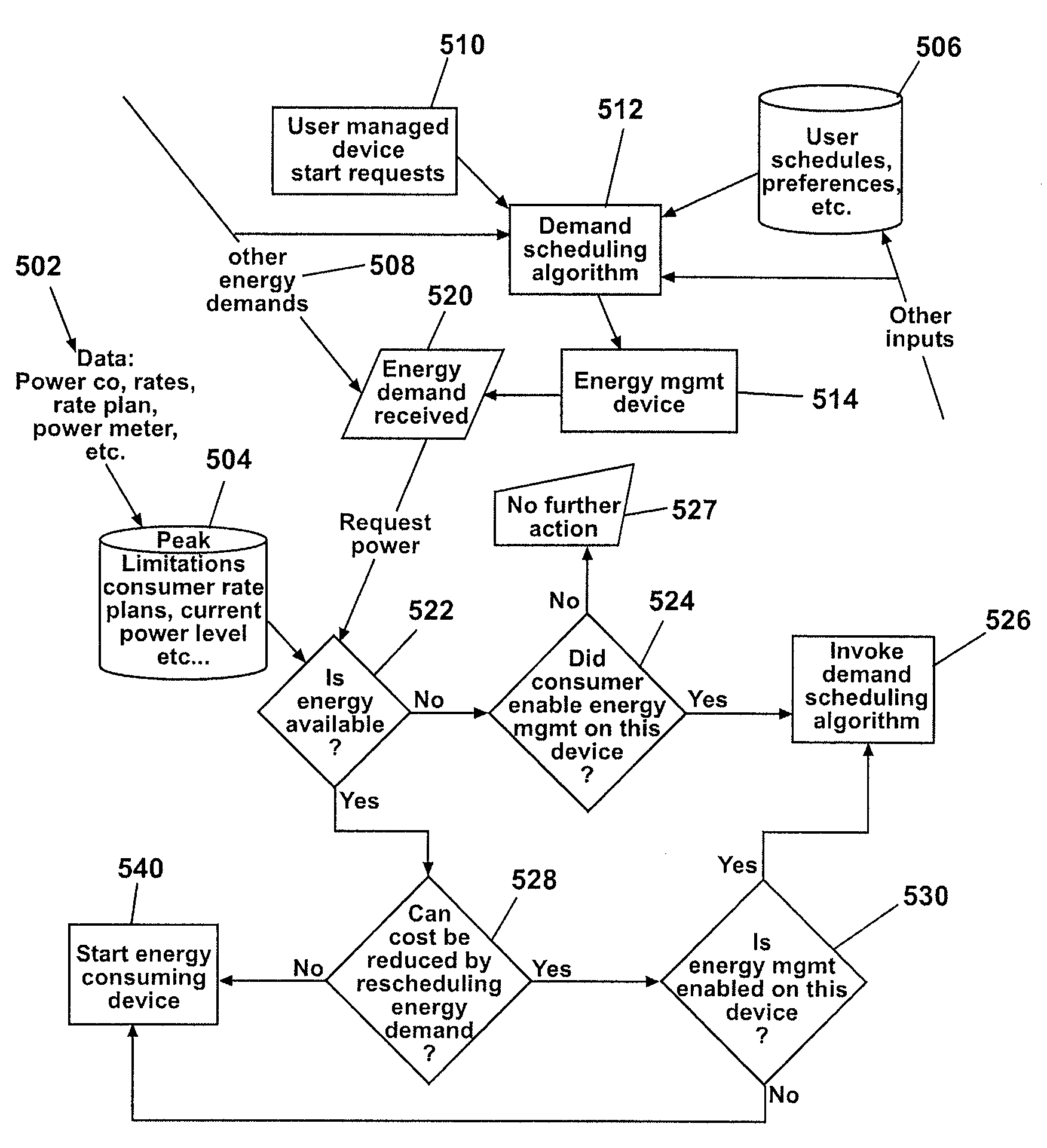
[0012]A specific aspect to the system is that there may be a plurality of inputs into a device that may make curtailment decisions to produce a variety of outputs to one or more energy consuming devices that are selected from at least two choices to control two curtailment levels. As part of the system, a controller may be placed in communication with energy consuming appliances. Request for energy may be received at the controller from the plurality of energy consuming appliances. Each request for energy may originate from an energy requesting appliance. The controller may be operated to provide energy to fewer than all of the energy requesting appliances to reduce a level of energy demand on an energy supply source.
[0013]Another aspect of this invention is that a controller in logical communication with an appliance may make an intelligent decision about control of the appliance after balancing a plurality of inputs selecting inputs selected from a group consisting of a power rate schedule, household status, personal preferences, curtailment requests from a power supplier, power requests and usage from other household appliances, power usage grants from a power supplier.

Problems solved by technology

This presents an unobvious opportunity to facilitate residential energy management.

Method used


Image

  • Total home energy management system
  • Total home energy management system
  • Total home energy management system

Examples


Embodiment Construction

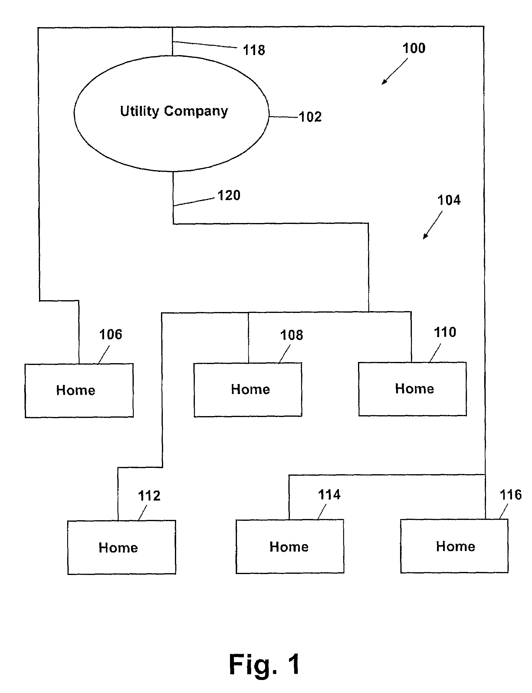
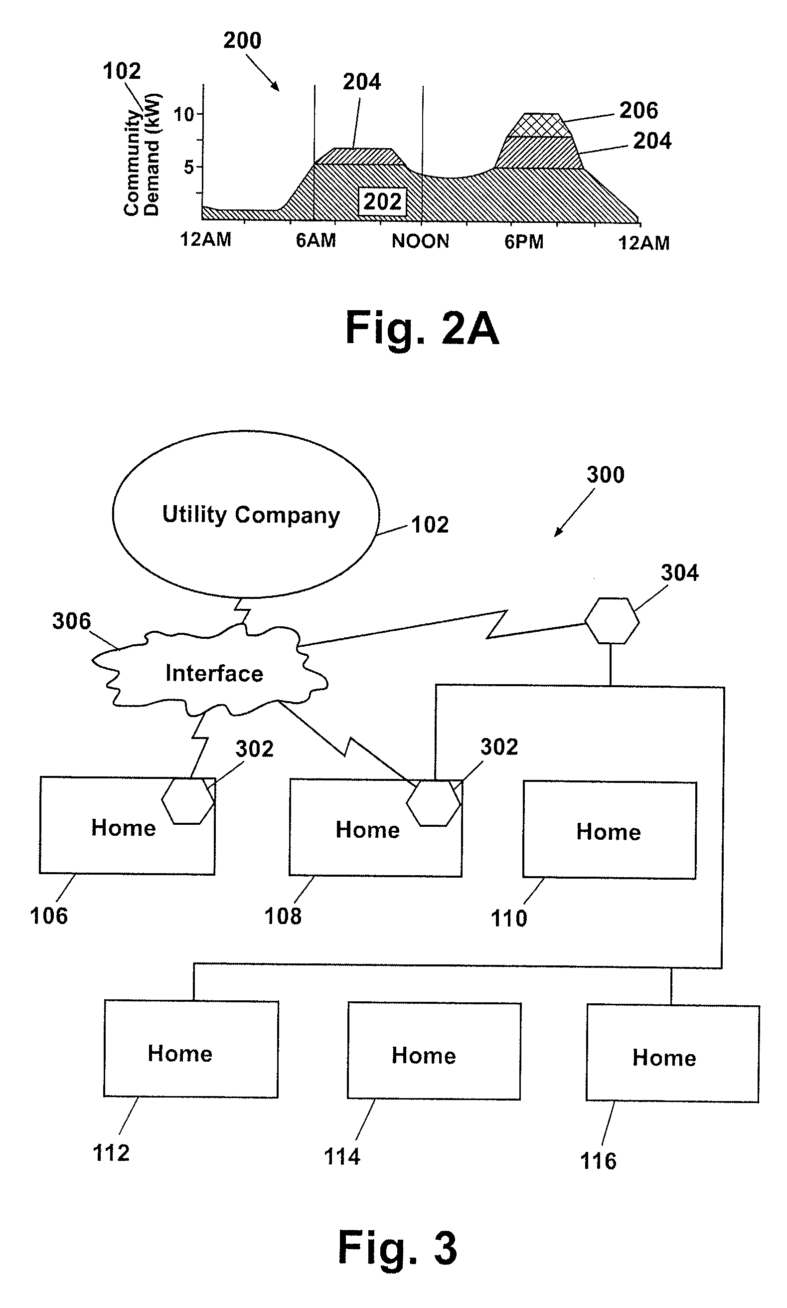
[0024]FIG. 1 is a schematic diagram of an energy distribution system 100. Included within the energy distribution system 100 may be an energy provider 102, such as a utility company, and a community 104 of homes, such as home 106, home 108, home 110, home 112, home 114, and home 116. The energy provider 102 may provide a supply of energy and be responsible for the delivery of that energy to homes 106-116. Each home 106-116 may include various energy consuming devices that utilize energy to operate. Examples of energy consuming devices include household appliances such as washers, dryers, ovens, dishwashers, refrigerators, freezers, hot water heaters, heating and cooling appliances, humidity control appliances, as well as lights, thermostats, ventilation and cooling infrastructure, and other pumps, heaters.

[0025]To deliver energy to one or more homes, the energy distribution system 100 may further include a power grid 118, connected to home 106, home 114, and home 116, and a power gr...


PUM


Abstract

A system that facilitates and implements energy savings decisions by a home owner. The system will provide a mechanism to reduce the peak level of energy demand. A controller in logical communication with energy consuming appliances responds to request for energy from energy consuming appliances and devices by permitting or curtailing energy supply to the appliances or devices based on evaluation of a plurality of logical considerations. The controller may be operated to provide energy to fewer than all of the energy requesting appliances to reduce the energy demand on an energy supply source, including the instantaneous peak demand.

Description

[0001]This application is a non-provisional of provisional application 60 / 389,013, filed on Jun. 13, 2002, the entire contents of which are hereby incorporated by reference.BACKGROUND OF THE INVENTION[0002]The present invention relates generally to managing energy consumption of home energy consuming devices through an energy demand controller.[0003]Just about all homes employ energy consuming appliances and other devices. Although each appliance in a home usually is operated independently from one another, each draws energy from the home energy distribution system. In turn, each home draws energy from the energy distribution system of an energy provider. During certain times of the day, such as morning or early evening, the draw on the energy provider energy distribution system is so great that the energy provider either brings on line additional power plants or buys additional power from other suppliers. This peak energy demand creates additional costs for the energy provider. The...

Claims


Application Information

Patent Timeline
Patent Type & Authority Patents(United States)
IPC IPC(8): G01R21/00G06F17/40H02J3/14H02J13/00
CPCH02J3/14H02J13/0055H02J13/0079H02J13/0086H02J2003/143Y04S20/242Y02B70/3225Y02B70/3266Y04S20/222Y04S20/224H02J2003/146H02J2310/14H02J2310/64H02J13/00004H02J13/00028Y02B70/30Y04S50/10H02J13/00001H02J2310/60H02J3/144H02J13/00006Y04S40/12Y02B90/20H02J13/00012
Inventor HORST, GALE RICHARDZHANG, JIANNONGSYVOKOZOV, ANDRIY DMYTROVYCH
Owner WHIRLPOOL CORP
Learn More