
Method and apparatus for land based seismic data acquisition

a technology for seismic data and land-based seismic, applied in seismic signal receivers, seismicology, instruments, etc., can solve the problems of large quantities of electrically conductive cabling that are expensive and difficult to handle, deploy or otherwise manipulate, and can present extreme challenges in certain environments, and achieve the effect of minimizing the likelihood

Active Publication Date: 2009-07-14
MAGSEIS FF LLC
View PDF79 Cites 60 Cited by
  • Summary
  • Abstract
  • Description
  • Claims
  • Application Information

AI Technical Summary

Benefits of technology

[0017]More specifically, the unit is self-contained such that all of the electronics are disposed within or on the case, including a geophone package, a seismic data recording device and a clock. A power source is either contained within the case, or may be attached externally to the case. The clock may be attached to a gimbaled platform having multiple degrees of freedom to minimize the effects of gravity on the clock.
[0026]In another aspect of the invention, the unit is activated prior to transportation out to the field and deactivated once retrieved, such that it is continuously acquiring data from before the time of deployment to after the time of retrieval. Likewise in one embodiment, the unit begins recording data prior to deployment. Systems that are activated and begin recording before deployment are thereby stabilized prior to the time when signal detection is desired. This minimizes the likelihood that an altered state in electronics operation will disrupt signal detection and recording or effect clock synchronization.

Problems solved by technology

As mentioned above, those skilled in the art will understand that certain environments can present extreme challenges for conventional methods of connecting and controlling seismic, such as congested or marine environments, rugged mountain environments and jungles or remote desert locations.
Difficulties may also arise in instances where the interconnected, hard-wired receiver array must be periodically moved to cover a larger area.
Whatever the case, each type of connection, whether via a physical cable or through wireless techniques, has its own drawbacks.
In cable telemetry systems, large arrays may result in large quantities of electrically conductive cabling that are expensive and difficult to handle, deploy or otherwise manipulate, as well as repair and maintain.
In hostile environments characterized by extreme or corrosive conditions, such as salt water, hot, sandy deserts or overgrown, damp jungles, costly cable armoring may be required.
Since it is generally not practical to hard wire strings of receivers to a cable, the more conventional technique is to use external cabling and connectors between strings of receivers and the telemetry cable.
This point of the connection between the cable and the sensor is particularly vulnerable to damage, especially in extreme or corrosive environments.
As such, many of the aforementioned drawbacks that arise from cabling system units together also exist when cabling various package components of an individual unit to one another.
In cases where either wireless technology is utilized or operation of units and their sensors is through pre-programming, control and monitoring of the units and sensors becomes more difficult.
One drawback to these prior art systems is the need to activate and deactivate the units for recording and operation, including data and quality control transmission.
However, external control may be undesirable since it requires signal transmission and additional components in the system.
Of course, any type of control signal cabling for transmission of electrical signals is undesirable because it adds a level of complexity to the handling and control of the unit and requires external connectors or couplings.
Such cabling and connectors are particularly susceptible to leakage and failure in extreme environments, whether the corrosive environment of transition zone water or the high temperature, corrosive environments of the desert.
A similar problem exists with units that utilize external electrical wiring to interconnect distributed elements of the unit, such as is taught in U.S. Pat. No. 5,189,642 and similar devices where the geophone package is separate from the electronics package.
Furthermore, to the extent the electronics of a system are distributed, the likelihood of malfunction of the system increases.
Such systems, of course, have limitations imposed by the characteristics of radio transmission, such as radio spectrum license restrictions, range limitations, line-of-sight obstructions, antenna limitations, data rate limitations, power restrictions, etc.

Method used


Image

  • Method and apparatus for land based seismic data acquisition
  • Method and apparatus for land based seismic data acquisition
  • Method and apparatus for land based seismic data acquisition

Examples


Embodiment Construction

[0035]In the detailed description of the invention, like numerals are employed to designate like parts throughout. Various items of equipment, such as fasteners, fittings, etc., may be omitted to simplify the description. However, those skilled in the art will realize that such conventional equipment can be employed as desired.

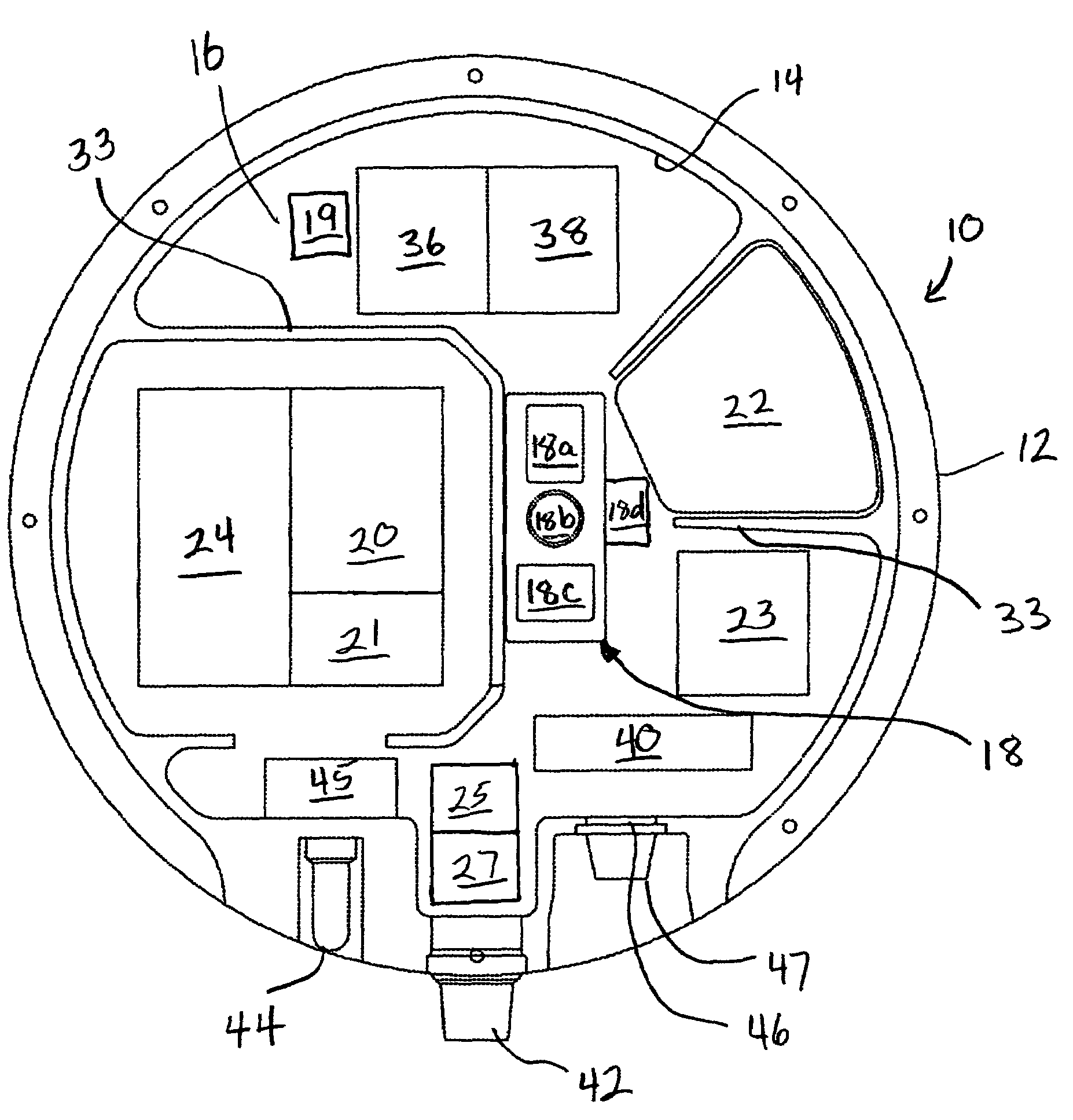
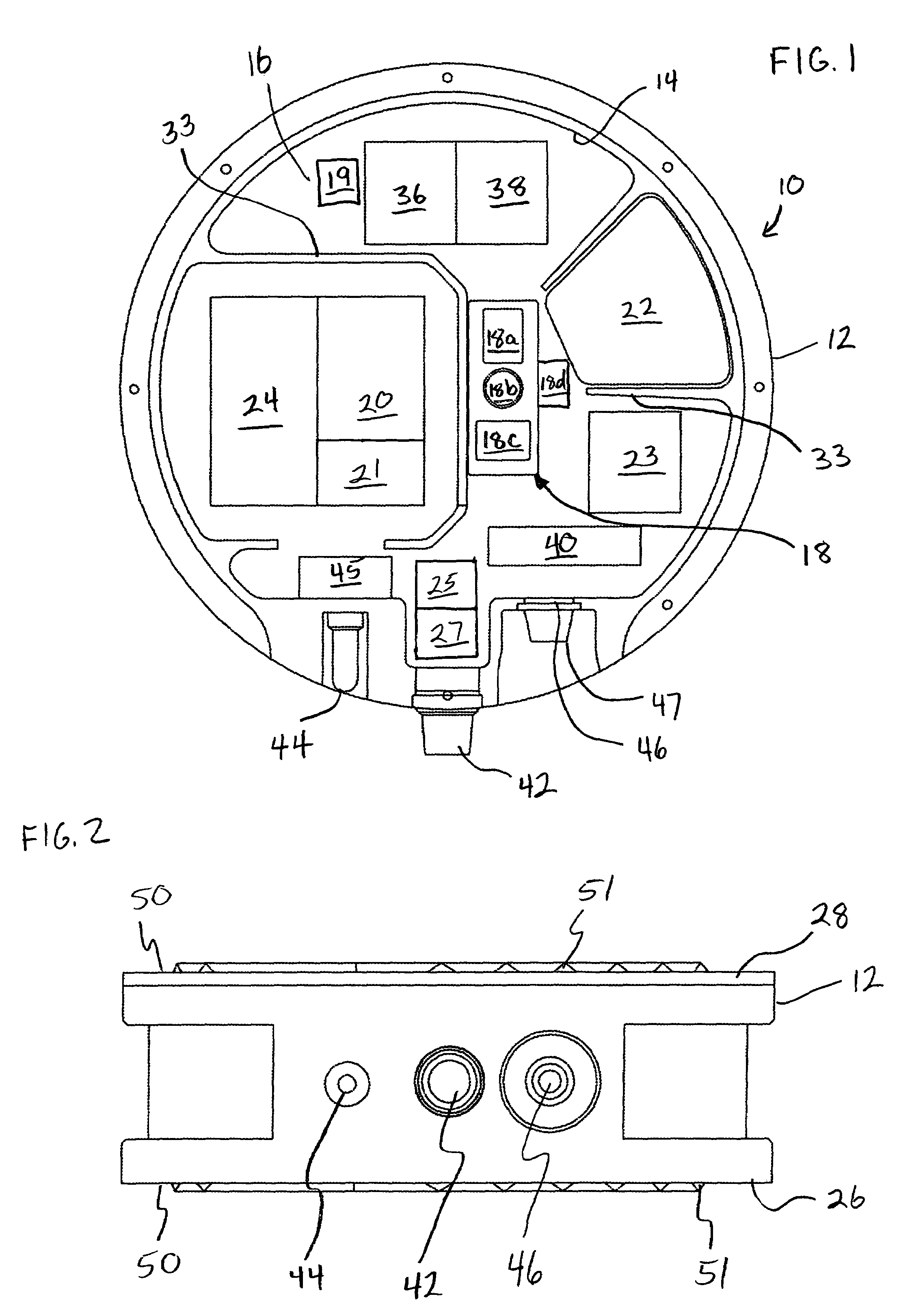
[0036]With reference to FIG. 1, there is shown a seismic data collection system or pod 10 of the invention. Pod 10 is comprised of a case 12 having a wall 14 defining an internal, compartment 16. Preferably, case 12 is sealed to prevent water, dust or other debris from migrating into compartment 16. Disposed within compartment 16 is at least one geophone 18, a clock 20, a power source 22, a control mechanism 23 and a seismic data recorder 24. In the embodiment, pod 10 is self-contained such that power source 22 meets all of the power requirements of pod 10. Likewise, control mechanism 23 provides all control functions for pod 10 eliminating the need for extern...


PUM


Abstract

A seismic exploration method and unit comprised of continuous recording, self-contained wireless seismometer units or pods. The self-contained unit may include a tilt meter, a compass and a mechanically gimbaled clock platform. Upon retrieval, seismic data recorded by the unit can be extracted and the unit can be charged, tested, re-synchronized, and operation can be re-initiated without the need to open the unit's case. The unit may include an additional geophone to mechanically vibrate the unit to gauge the degree of coupling between the unit and the earth. The unit may correct seismic data for the effects of crystal aging arising from the clock. Deployment location of the unit may be determined tracking linear and angular acceleration from an initial position. The unit may utilize multiple geophones angularly oriented to one another in order to redundantly measure seismic activity in a particular plane.

Description

CROSS REFERENCE TO RELATED APPLICATIONS[0001]This application claims priority under U.S. patent application Ser. No. 10 / 448,547, filed on May 30, 2003.BACKGROUND OF THE INVENTION[0002]The present invention relates to the field of seismic exploration. More particularly, the invention relates to a method and apparatus for seismic exploration, and most particularly to a self-contained, land based or marine deployable seismometer system.[0003]Seismic exploration generally utilizes a seismic energy source to generate an acoustic signal that propagates into the earth and is partially reflected by subsurface seismic reflectors (i.e., interfaces between subsurface lithologic or fluid layers characterized by different elastic properties). The reflected signals (known as “seismic reflections”) are detected and recorded by seismic receivers located at or near the surface of the earth, thereby generating a seismic survey of the subsurface. The recorded signals, or seismic energy data, can then ...

Claims


Application Information

Patent Timeline
IPC IPC(8): G01V1/16
CPCG01V1/16G01V1/24G01V2200/12
Inventor RAY, CLIFFORD H.FISSELER, GLENN D.HAYGOOD, HAL B.
Owner MAGSEIS FF LLC
Learn More