
Fuel cell apparatus and method for controlling fuel

a fuel cell and fuel technology, applied in the field of fuel cells, can solve the problems and achieve the effect of reducing the output of the fuel cell

Inactive Publication Date: 2009-07-14
SONY CORP
View PDF15 Cites 6 Cited by
  • Summary
  • Abstract
  • Description
  • Claims
  • Application Information

AI Technical Summary

Benefits of technology

[0008]The present invention provides a fuel cell apparatus and a method for controlling a fuel cell, which can prevent the problems of the low output during the operation or at the start of operation.
[0010]Fuel cells are known to be problematic in that the electrolyte membrane is dried to lower the ion-exchange characteristics when lowering the load current or increasing the air feed rate during the operation or when allowing the fuel cell to stand for a long time, so that the output of the fuel cell is considerably lowered. In the present invention, a load control portion for permitting a load on the fuel cell to vary depending on the output state of the fuel cell or an air feeding control portion is provided in the fuel cell and controlled to increase the load current or suppress the air feeding when the output characteristics are lowered, the internal resistance value is increased, and / or the like thus solving the above problem.
[0011]In an embodiment of the present invention, the bypass circuit is provided and therefore, if, for example, the output characteristics decreases due to drying of the oxygen electrode, the bypass circuit is operated and controlled to permit a load current on the fuel cell to vary depending on the output state, making it possible to intentionally increase the amount of water formed. The formed water can suppress drying of the oxygen electrode and also let the oxygen electrode be in an appropriate wet state. In one embodiment of the present invention, the first predetermined value is in the range of, for example, about 0.01 V to about 0.8 V per electricity generator, and set to be, for example, about 1% to about 95% of a usual electromotive force. Alternatively, the first predetermined value may be set to be a value by the amount lowered from the electromotive force that is typically or generally produced during operations.
[0013]In the fuel cell according to an embodiment, air is fed to the oxygen electrode while feeding a fuel to the fuel electrode to cause proton conduction in the electrolyte. The amount of the proton conduction varies in accordance with the load current connected to the fuel cell, and, if the load current value is smaller, the output voltage increases to reduce heat generation and, conversely, if the load current is larger, the amount of the proton conduction increases and an amount of formed water increases. The reason for this is that the reaction on the oxygen electrode is promoted. For example, if the output characteristics are lowered due to drying of the oxygen electrode, the load control portion is operated and controlled to permit a load current on the fuel cell to vary depending on the output state, making it possible to intentionally increase the amount of water formed. The water formed can suppress drying of the oxygen electrode as well as let the oxygen electrode be in an appropriate wet state.
[0017]In the fuel cell, air is fed to the oxygen electrode while feeding a fuel to the fuel electrode to cause proton conduction in the electrolyte. The amount of the proton conduction varies depending on the load current connected to the fuel cell, and, if the load current becomes larger, the amount of the proton conduction increases and an increased amount of water is formed. The feed rate of air fed to the oxygen electrode of the fuel cell is ideally operated so that, for example, during the operation, the amount of water formed and the amount of moisture evaporated which depends on the air feed rate are steadily in equilibrium, but the air feed rate is changed by the air feeding control portion and controlled so as to, for example, suppress evaporation of moisture from the fuel cell surface, thus making it possible to suppress drying of the oxygen electrode and let the oxygen electrode be in an appropriate wet state.
[0019]If the output characteristics or internal resistance characteristics of the fuel cell change, the feed rate of air fed to the fuel cell is controlled to be smaller than usual (i.e., under usual, normal and / or standard operating conditions), and thus, not only can drying of the oxygen electrode in the fuel cell be suppressed, but also the oxygen electrode can be in an appropriate wet state, and monitoring the necessity of this directly from the output characteristics or internal resistance characteristics of the fuel cell makes it possible to quickly deal with the matter even if a failure occurs in the electricity generation. In the present specification, the measurement of electromotive force encompasses measurements and calculations of an output current and an internal resistance of the fuel cell or similar parameters.

Problems solved by technology

Fuel cells are known to be problematic in that the electrolyte membrane is dried to lower the ion-exchange characteristics when lowering the load current or increasing the air feed rate during the operation or when allowing the fuel cell to stand for a long time, so that the output of the fuel cell is considerably lowered.

Method used


Image

  • Fuel cell apparatus and method for controlling fuel
  • Fuel cell apparatus and method for controlling fuel
  • Fuel cell apparatus and method for controlling fuel

Examples


Embodiment Construction

[0039]The present invention relates to fuel cells. More specifically, the present invention relates to a fuel cell apparatus having an electrolyte disposed between a fuel electrode and an oxygen electrode, wherein a fuel, such as hydrogen, as well as air are fed to the fuel cell, to generate the desired electromotive fuel and method for controlling the fuel cell.

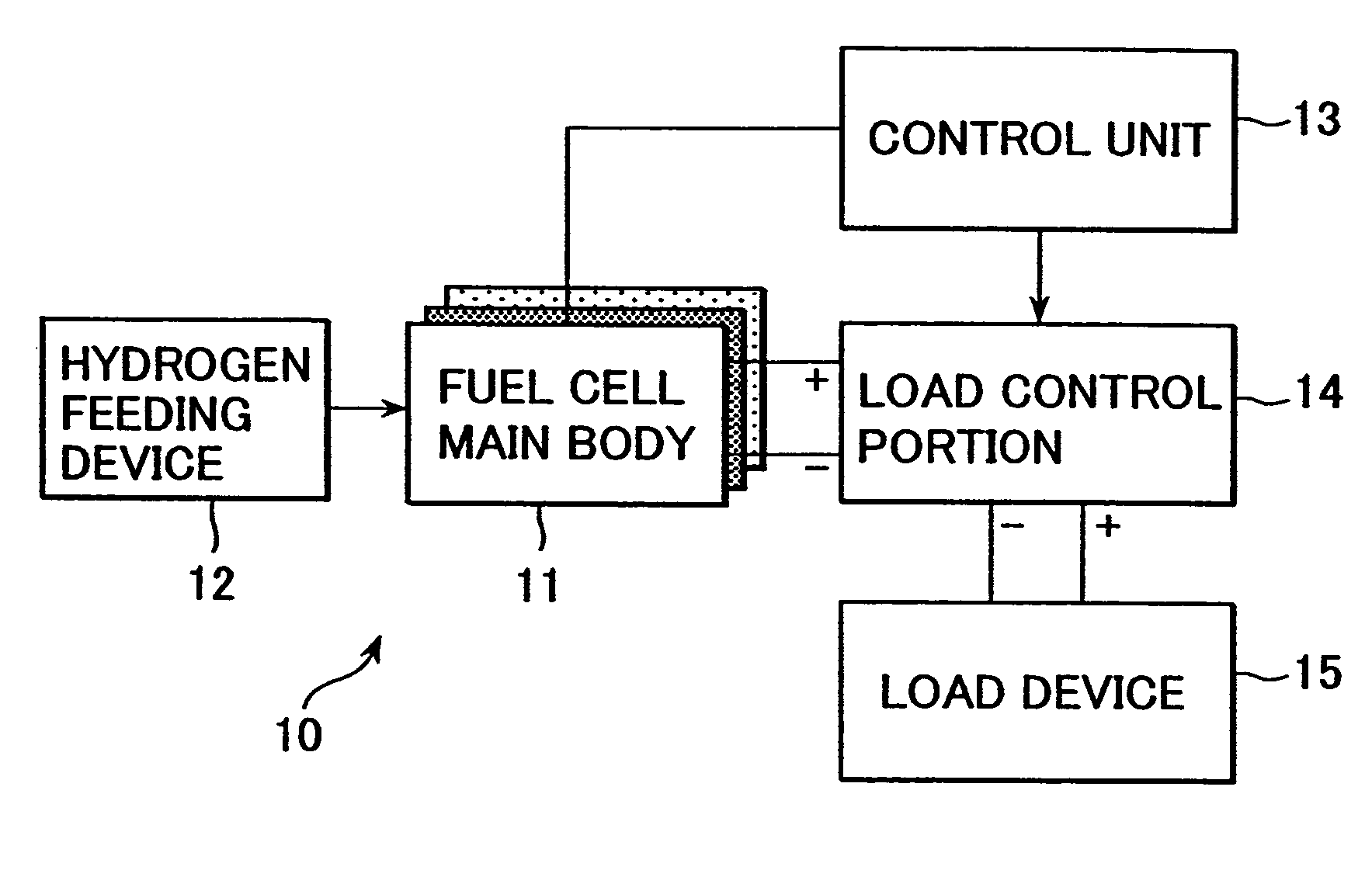
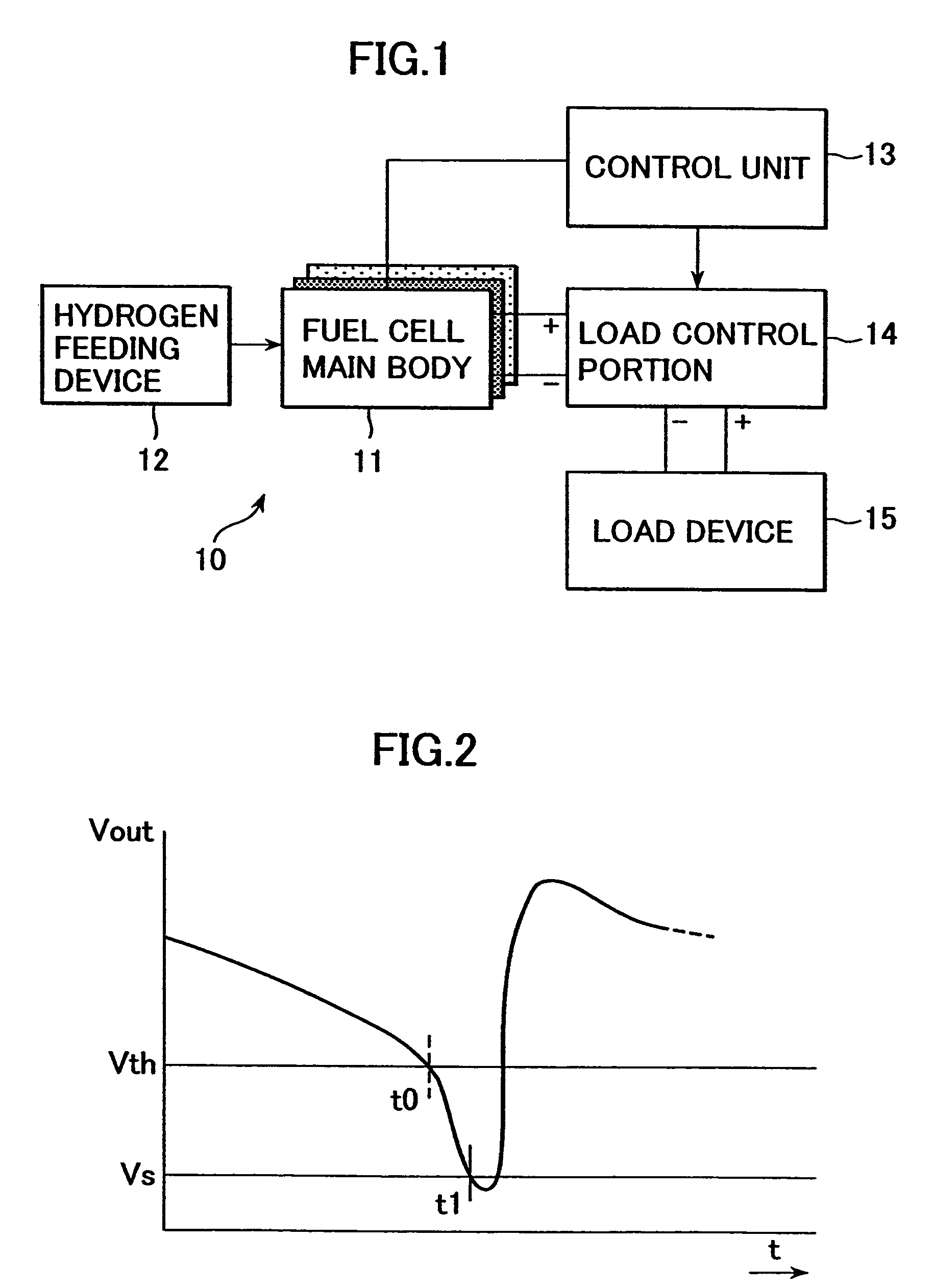
[0040]A preferred embodiment of a fuel cell apparatus of the present invention will be described with reference to the drawings. FIG. 1 is a block diagram showing a fuel cell apparatus according to the present embodiment. A fuel cell apparatus 10 of the present embodiment in an embodiment has a fuel cell main body 11 for generating electromotive force, a control unit 13 for controlling a load, and a load control portion 14, connected to the fuel cell main body 11, for permitting a value of a load on the fuel cell main body 11 to vary. Electromotive force is generally supplied to a load device 15 through the load control port...


PUM


Abstract

The present invention relates to a fuel cell. The fuel cell includes an electricity generator which has an oxygen electrode, a fuel electrode, and a solid polymer type electrolyte membrane disposed between the oxygen electrode and the fuel electrode, and a method for controlling the fuel cell.

Description

CROSS REFERENCES TO RELATED APPLICATIONS[0001]The present application claims priority to Japanese Patent Document Nos. P2002-077658 filed on Mar. 20, 2002; P2002-077719 filed on Mar. 20, 2002; and P2003-053612 filed on Feb. 28, 2003, the disclosures of which are herein incorporated by reference.BACKGROUND OF THE INVENTION[0002]The present invention relates to fuel cells. More specifically, the present invention relates to a fuel cell apparatus having an electrolyte disposed between a fuel electrode and an oxygen electrode, wherein a fuel, such as hydrogen, as well as air are fed to the fuel cell to generate desired electromotive force, and a method for controlling the fuel cell.[0003]In general a fuel cell is an apparatus in which an electricity generator generates electric power by supplying fuel fluid, such as hydrogen gas or methanol, and a solid polymer type fuel cell generally has a structure such that a proton conductor membrane is disposed between an oxygen-side electrode and...

Claims


Application Information

Patent Timeline
IPC IPC(8): H01M8/00H01M8/04H01M8/06H01M8/10H01M16/00
CPCH01M8/04119H01M8/04223H01M8/04291H01M8/04492H01M8/04529H01M8/04634H01M8/04753H01M8/0485H01M8/0491H01M8/04559Y02E60/50H01M2008/1095H01M8/04225H01M8/04302H01M8/04H01M8/06
Inventor TAHARA, MASAHIKO
Owner SONY CORP
Learn More