
Surgical instrument having fluid actuated opposing jaws

a technology of opposing jaws and surgical instruments, which is applied in the direction of surgical staples, surgical forceps, paper/cardboard containers, etc., can solve the problem of complicated and complicated actuation control down the elongated sha

Active Publication Date: 2009-07-14
ETHICON ENDO SURGERY INC
View PDF121 Cites 1953 Cited by
  • Summary
  • Abstract
  • Description
  • Claims
  • Application Information

AI Technical Summary

Benefits of technology

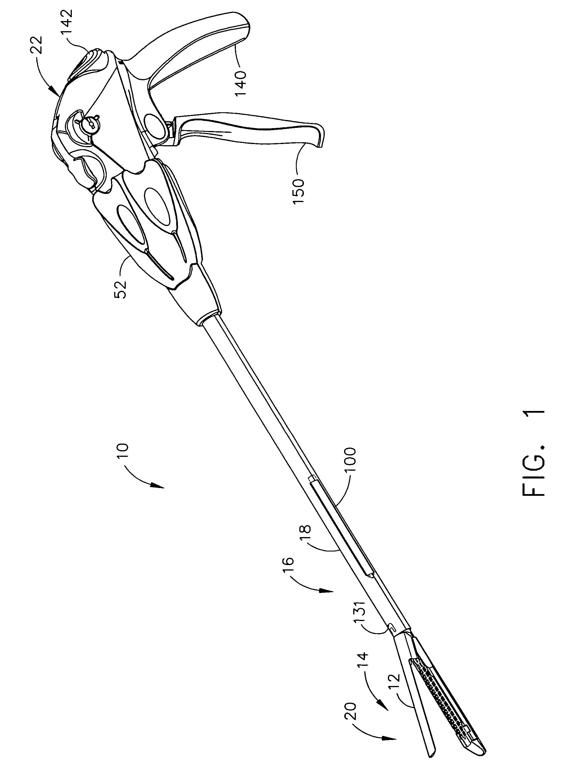
The invention is a surgical instrument that can be used for minimally invasive surgeries. It has a handle that positions an end effector through a surgical opening via an elongate shaft. The end effector has a pair of pivoting members that can be opened and closed upon tissue. Once closed, a firing bar that is received for reciprocating a longitudinal firing motion in an elongate shaft transfers a longitudinal firing motion from a handle to actuate a staple cartridge and to sever the clamped tissue in the end effector. The instrument has a fluid actuator that is positioned in a lever cavity and is actuated by fluid transferred through a fluid conduit in the elongate shaft. The lever of a tissue contacting member extends proximally into the lever cavity from a pivotal connection with a second tissue contacting member. The fluid transfer advantageously effects pivotal movement of the pair of tissue contacting members. The technical effects of the invention are that it allows for small cross section shafts that can perform important surgical operations and it has a fluid actuator that can open and close the end effector with a single stroke, making it easier to use for surgeons.

Problems solved by technology

Providing an actuating control down the elongate shaft with sufficient strength is complicated by a design goal of minimum cross sectional area so as to pass through a small cannula of a trocar.

Method used


Image

  • Surgical instrument having fluid actuated opposing jaws
  • Surgical instrument having fluid actuated opposing jaws
  • Surgical instrument having fluid actuated opposing jaws

Examples


Embodiment Construction

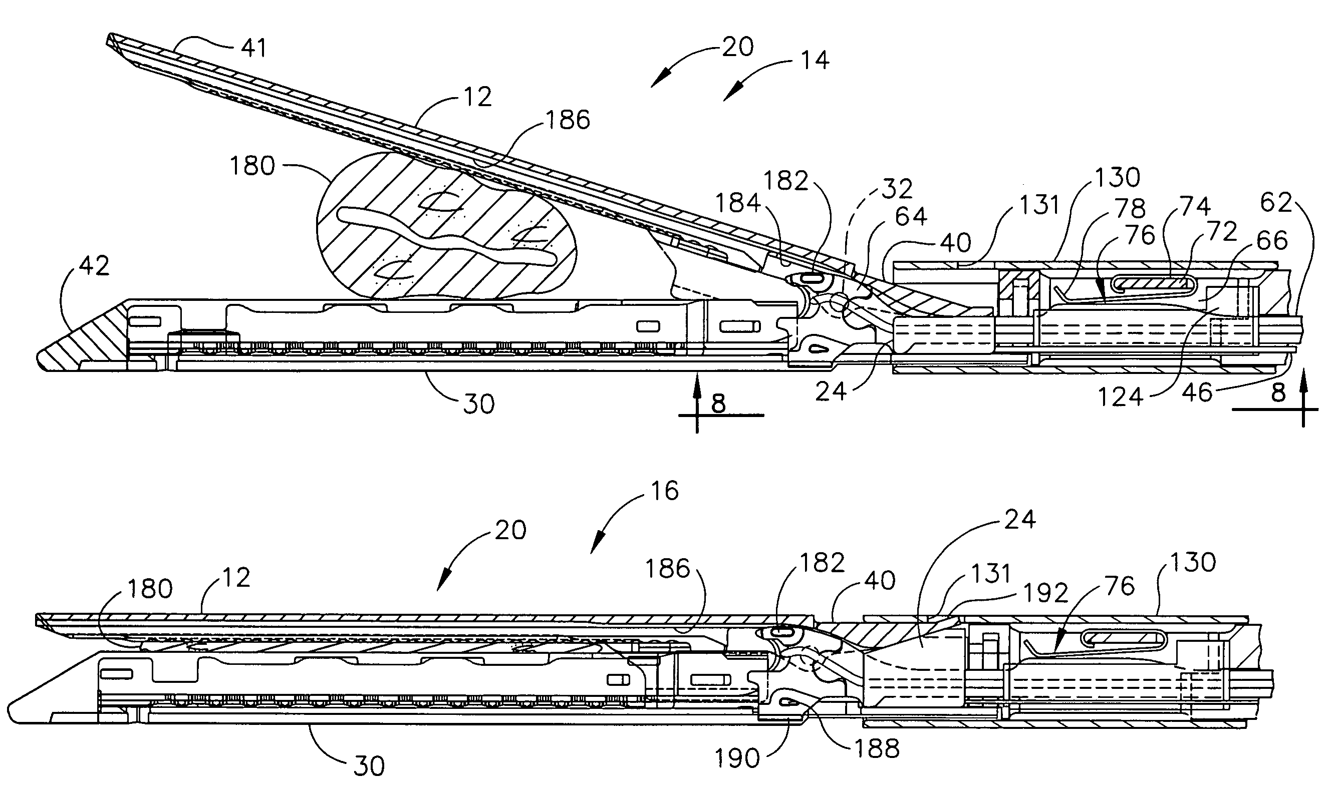
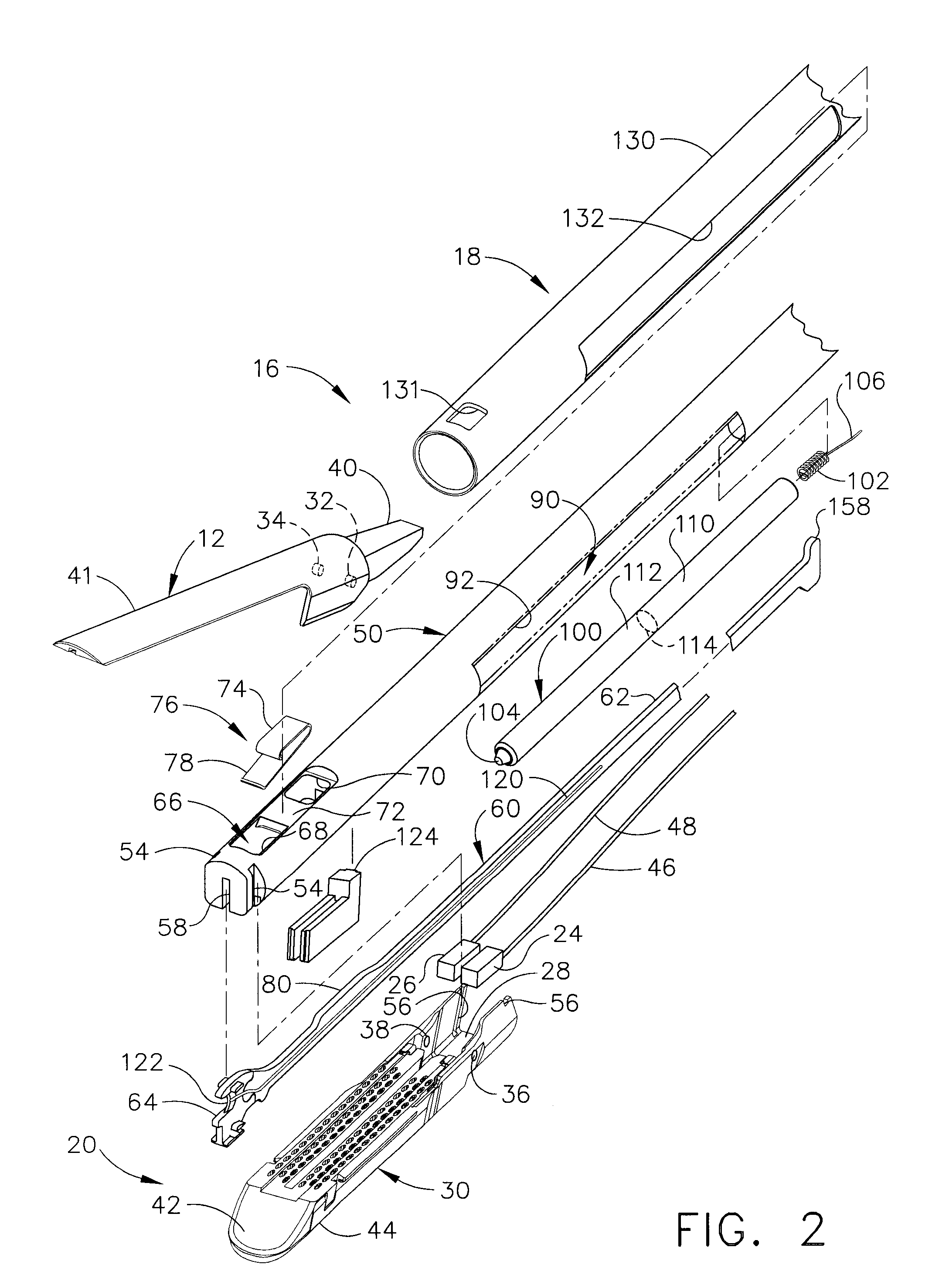
[0034]Turning to the Drawings, wherein like numerals denote like components throughout the several views, FIGS. 1-2 show a surgical stapling and severing instrument 10 that is capable of practicing the unique benefits of the present invention, including both fluid actuation (e.g., opening, closing / clamping) of an upper jaw (anvil) 12 of an end effector 14 as well as dispensing a medical substance onto tissue as severed. Fluid actuation of the end effector 14 provides a range of design options that avoid some design limitations of traditional mechanical linkages. For example, instances of binding or component failure may be avoided. Further, dispensing liquids onto severed tissue allows for a range of advantageous therapeutic treatments to be applied, such as the application of anesthetics, adhesives, cauterizing substances, antibiotics, coagulant, etc.

[0035]With particular reference to FIG. 2, the surgical stapling and severing instrument 10 includes an implement portion 16 formed b...


PUM

PropertyMeasurementUnit
voltage potentialaaaaaaaaaa
flexibleaaaaaaaaaa
pressureaaaaaaaaaa

Abstract

A surgical stapling and severing instrument enables minimally invasive surgical procedures by having upper and lower jaws (i.e., anvil and staple channel) that are positioned with an elongate shaft and handle through surgical openings, and in particular through a cannula of a trocar. A pair of fluid actuator bladders (lift bags) are positioned in the staple channel beneath a proximally projecting lever tray so that transfer of fluid from the handle causes closing and clamping of the anvil. The bi-directional fluid control may be mechanically produced at the handle or by activating an electroactive polymer actuator. Once firing is sensed, an EAP plunger in a medical substance syringe inserted into the elongate shaft is activated to dispense a medical substance (e.g., anesthetics, adhesives, cauterizing substances, antibiotics, etc.) and is guided along a firing bar to a cutting surface of an E-beam placing the substance on tissue as severed.

Description

CROSS REFERENCE TO RELATED APPLICATIONS[0001]This application is a continuation-in-part of commonly owned U.S. patent application Ser. No. 11 / 061,908 entitled “SURGICAL INSTRUMENT INCORPORATING A FLUID TRANSFER CONTROLLED ARTICULATION MECHANISM” to Kenneth Wales and Chad Boudreaux, filed on Feb. 18, 2005, now abandoned, the disclosure of which is hereby incorporated by reference in its entirety.FIELD OF THE INVENTION[0002]The present invention relates in general to surgical stapler instruments that are capable of applying lines of staples to tissue while cutting the tissue between those staple lines and, more particularly, to improvements relating to stapler instruments and improvements in processes for forming various components of such stapler instruments.BACKGROUND OF THE INVENTION[0003]Surgical instruments for minimally invasive surgery are increasingly relied upon to reduce the hospital stay and recovery time for various surgical procedures. Many of these surgical instruments i...

Claims


Application Information

Patent Timeline
Patent Type & Authority Patents(United States)
IPC IPC(8): A61B17/072A61B17/068
CPCA61B17/068A61B17/07207A61B17/115A61B17/29A61B17/320016A61B17/3201A61B17/00491A61B2017/2932A61B2017/00539A61B2017/00544A61B2017/00893A61B2017/07214A61B2017/07285A61B2017/2912A61B17/072A61B17/122
Inventor WALES, KENNETH S.SHELTON, IV, FREDERICK E.
Owner ETHICON ENDO SURGERY INC
Learn More