Light emitting diode signaling device and method of providing an indication using the same

a technology of light-emitting diodes and signaling devices, which is applied in the direction of semiconductor devices for light sources, lighting and heating apparatus, lighting applications, etc., can solve the problems of increasing the manufacturing, operating and maintenance costs of led signaling devices, and prohibiting retrofitting some existing incandescent signaling devices

Active Publication Date: 2009-06-30
ANSALDO STS USA INC
View PDF24 Cites 23 Cited by
  • Summary
  • Abstract
  • Description
  • Claims
  • Application Information

AI Technical Summary

Benefits of technology

[0008]These needs and others are met by the present invention, which is directed to an improved LED signaling device. The improved LED signaling device employs a number of LEDs arranged in a specific pattern. At least some of the LEDs are received in a corresponding reflective cavity with an associated output angle. The LED signaling device also employs first and second lenses. The first lens collects the light emitted by the LEDs and disperses the light such that the second lens is flooded. The second lens collects the light dispersed by the first lens and collimates the light. The type of LEDs used, their specific pattern, the specific output angles of their corresponding reflective cavities, and the combination of the first and second lenses insure that the LED signaling device meets or exceeds the minimum luminous output intensity requirements and uniformity requirements.

Problems solved by technology

Older generation LEDs used in LED signaling devices, however, have several limitations.
The use of large numbers of LEDs, however, increases the manufacturing, operating, and maintenance costs of the LED signaling device.
Additionally, the amount of space needed to accommodate the large number of LEDs make retrofitting some existing incandescent signaling devices prohibitive.
The use of fewer LEDs, however, may cause uniformity problems.
Specifically, the use of fewer LEDs may undesirably increase the potential for viewing one or more of the LEDs as an individual point source and / or may undesirably increase the potential of creating shadows.

Method used


Image

  • Light emitting diode signaling device and method of providing an indication using the same
  • Light emitting diode signaling device and method of providing an indication using the same
  • Light emitting diode signaling device and method of providing an indication using the same

Examples


Embodiment Construction

[0043]Directional phrases used herein, such as, for example, left, right, clockwise, counterclockwise, top, bottom, up, down, and derivatives thereof, relate to the orientation of the elements shown in the drawings and are not limiting upon the claims unless expressly recited therein.

[0044]As employed herein, the term “number” shall mean one or more than one and the singular form of “a”, “an”, and “the” include plural referents unless the context clearly indicates otherwise.

[0045]As employed herein, the statement that two or more parts are “connected” or “coupled” together shall mean that the parts are joined together either directly or joined together through one or more intermediate parts. Further, as employed herein, the statement that two or more parts are “attached” shall mean that the parts are joined together directly.

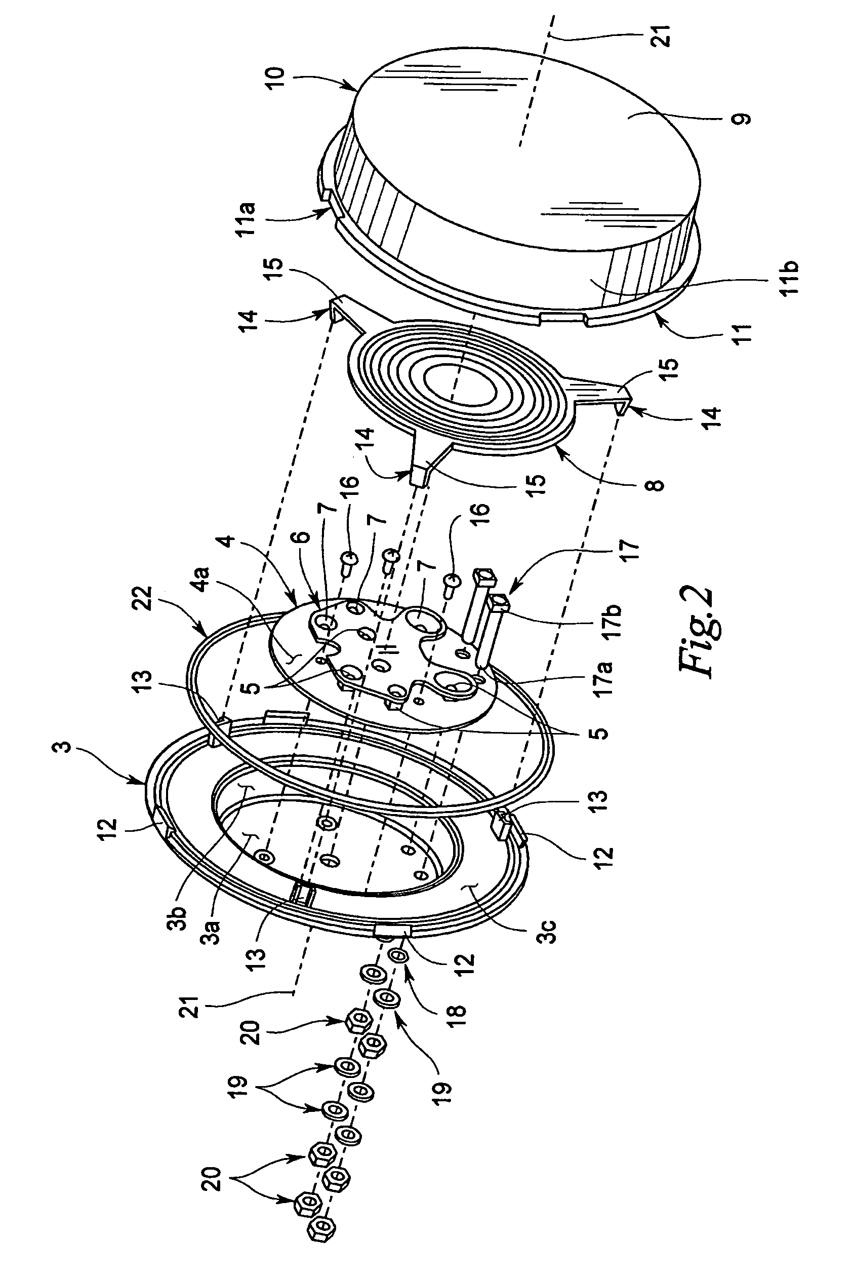
[0046]Referring to FIGS. 1-3, an LED signaling device 1 is illustrated according to one embodiment. The LED signaling device 1 comprises a back plate 3, a circu...


PUM


Abstract

An improved LED signaling device employing a number of LEDs arranged in a specific pattern. At least some of the LEDs are received in a corresponding reflective cavity with an associated output angle. The LED signaling device also employs first and second lenses. The first lens collects the light emitted by the LEDs and disperses the light such that the second lens is flooded. The second lens collects the light dispersed by the first lens and collimates the light. The type of LEDs used, their specific pattern, the specific output angles of their corresponding reflective cavities, and the combination of the first and second lenses insure that the LED signaling device meets or exceeds the minimum luminous output intensity requirements and uniformity requirements.

Description

BACKGROUND OF THE INVENTION[0001]1. Field of the Invention[0002]The present invention relates generally to signaling devices and more particularly to an improved light emitting diode signaling device and a method of providing an indication using the same.[0003]2. Background Information[0004]Light emitting diodes (LEDs) are replacing incandescent bulbs in various types of signaling devices such as, for example and without limitation, traffic signals, railroad crossing signals, and railroad wayside signals. An LED signaling device (i.e., a signaling device incorporating LEDs as an indication source) consumes less power, provides increased reliability, and requires less maintenance than a comparable incandescent signaling device (i.e., a signaling device incorporating an incandescent bulb as an indication source).[0005]Older generation LEDs used in LED signaling devices, however, have several limitations. For example, the luminous output intensity of individual older generation LEDs is...

Claims


Application Information

Patent Timeline
Patent Type & Authority Patents(United States)
IPC IPC(8): F21V7/00
CPCF21V5/045F21K9/00F21W2111/00F21Y2101/02F21Y2115/10F21K9/69
Inventor WEDELL, MARK T.
Owner ANSALDO STS USA INC
Why Eureka
Try Eureka