
Sealing device

a sealing device and sealing technology, applied in the direction of transit packaging, external support, paper/cardboard containers, etc., can solve the problems of contaminating or polluting the package and any substance or product contained in the package, difficult maintenance and cleaning of the sealing apparatus, and reducing the sterilization effect of the package and its conten

Inactive Publication Date: 2009-06-23
TETRA LAVAL HLDG & FINANCE SA
View PDF20 Cites 0 Cited by
  • Summary
  • Abstract
  • Description
  • Claims
  • Application Information

AI Technical Summary

Benefits of technology

[0009]The main objects of the present invention are to fold and seal packages by using a novel sealing apparatus and a novel method of operating the sealing apparatus with a simpler, faster, more hygienic, and more reliable transversal folding and sealing of the packages.
[0012]By providing a packaging apparatus with a sealing apparatus according to the invention and operating the sealing apparatus by the suitable above-mentioned method, the following main advantages are obtained: the folding and sealing of each package are performed more accurately and easier, thereby reducing adjustment time and giving increased productivity; cleaning of the sealing apparatus is performed easier, faster, and better, whereby the package and its content are kept sterilized creating a higher shelf-life for the package and its contained substance; and, the sealing apparatus is easier to disassemble or dismount and maintain, thereby also giving increased productivity.
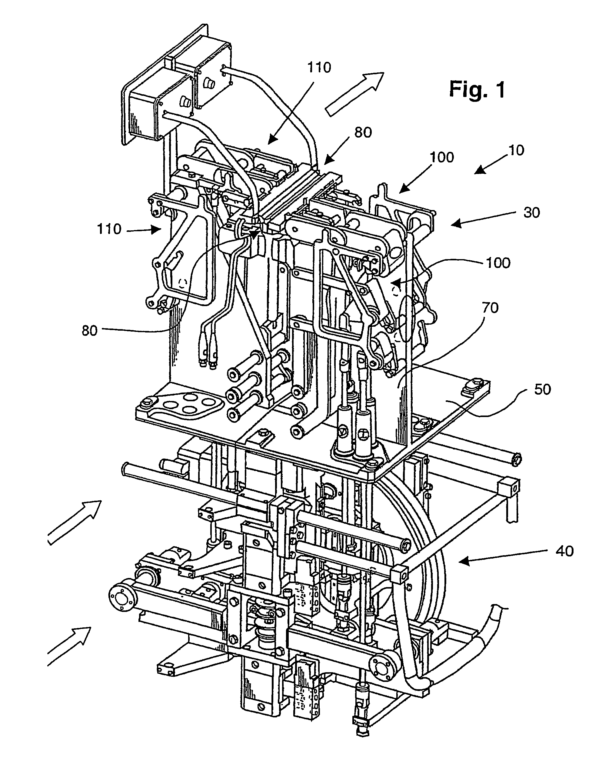
[0024]In a further embodiment each half of the second pair of linkage arrangements comprises a first and a second arm, which first and second arms being connected to each other in first ends thereof and provided with the forming means for forming each package adjacent the open end thereof, which first arm in a second end is pivotably connected to the second carrier by a link and which between the first and second ends is provided with a fixed pivot point, and which second arm in a second end is fixed and which in between the first and second ends is provided with a fixed pivot point. This geometry of the second linkage arrangements give rise to a “wave”-like motion of the forming means when they are moved towards and from the package, i.e. the the ends of the linkage arrangements which are provided with the forming means will make a tilting motion during the movement. The tilting is accomplished in that the first end of the first arm during a part of the movement moves to a position which is lower than the position of the first end of the second arm, seen in relation to the package fin created during sealing. The tiliting motion takes place in the end of the movement towards the package and in the beginning of the movement from the package. This “wave”-like motion of the forming means is advantageous in that it minimises the risk of damaging a portion of the package near the seal, i.e. near the fin, for example the triangular corner flaps present in many known carton packages. This is especially useful when the forming means are moved from the package since the package has then been sealed and is less flexible due to the rigid fin.
[0026]Preferably, the third carrier is connected to the cam curve disc via a fourth carrier. The fourth carrier is connected to the third carrier via an actuation member, which actuation member is adapted to change the mutual distance between the third and fourth carriers along the guide for biasing the sealing means for closing and sealing the open end of each package. By providing an actuation member an additional sealing force is obtained which further secures the creation of a satisfactory seal.
[0028]Advantageously, the fixed pivot point of the arm of each half of the first linkage arrangements and the fixed pivot point of the arm of each half of the third linkage arrangement are arranged substantially at the fixed pivot point of the first arm and the fixed second end of the second arm of each half of the second linkage arrangements in the vertical direction. By providing an apparatus with the above-mentioned features further advantages, in addition to the above-mentioned advantages, are obtained. The carriers and the cam curve, being the drive equipment, can be separated from the sealing equipment by for example a middle section. By providing the above-mentioned substantially “coinciding” points (fixed point, pivot points etc) in or near the middle section only few pivot points will be present in the area near the package. Thus, the risk of disturbing the air flows provided to keep the package and its content sterilized is minimized and any dirt from the drive equipment can be shielded from the area near the package. This is an advantage when the package content is exceptionally sensitive.

Problems solved by technology

A disadvantage with U.S. Pat. No. 4,546,592 is that wear of moving parts may create a bigger risk of having material on the fingers and their actuation means coming loose and falling down into the package before it is folded and sealed.
Moreover, lubricants or any other contaminations may also fall into the open end of the package before sealing, thereby contaminating or polluting the package and any substance or product contained in the package.
Another problem is that the movable parts are difficult to disassemble or dismount from each other due to a complicated structure, whereby any maintenance and cleaning of the sealing apparatus are difficult and time-consuming creating a higher cost per package and / or product and a shorter working life for the apparatus.

Method used


Image

  • Sealing device
  • Sealing device
  • Sealing device

Examples


Embodiment Construction

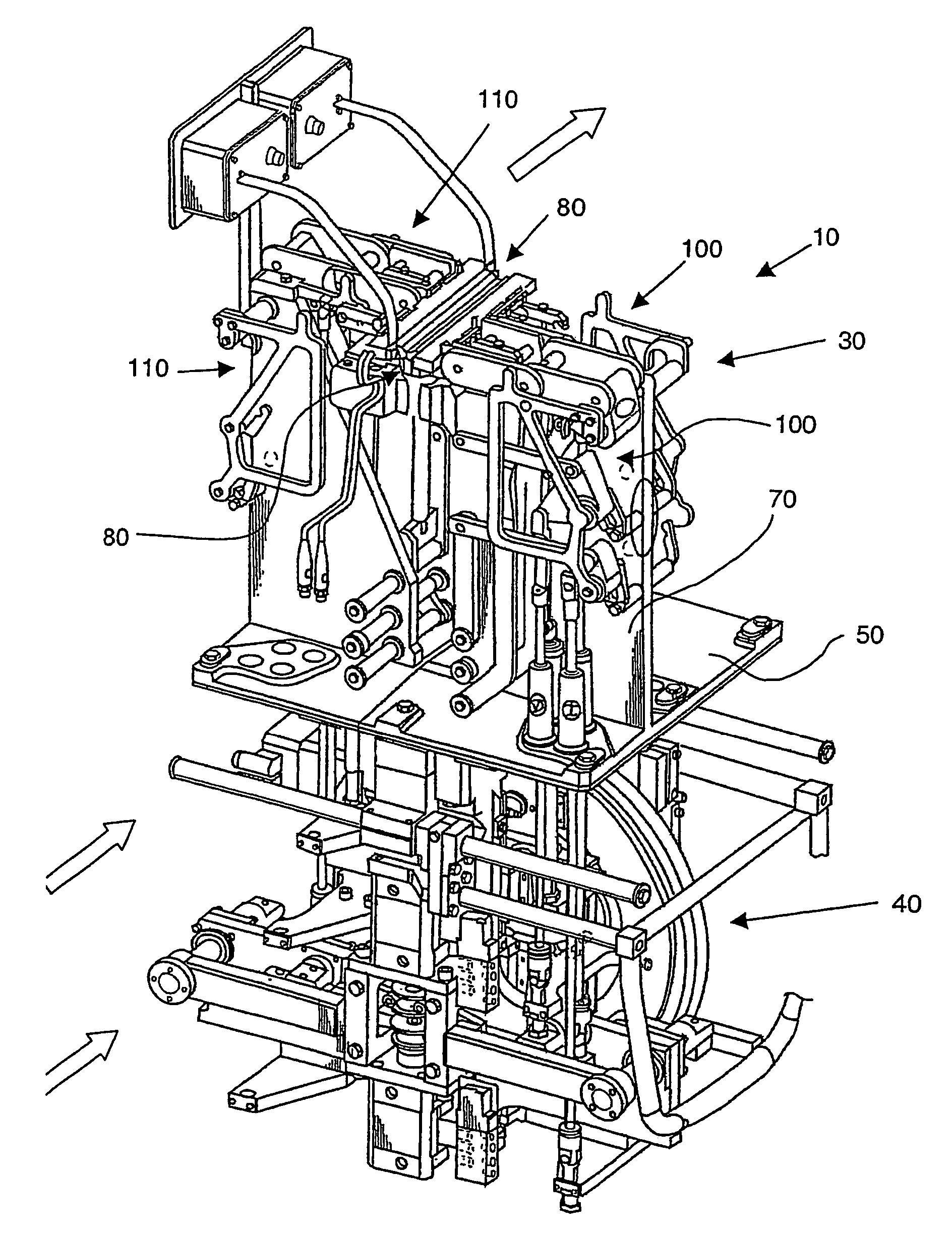
[0042]FIG. 1 shows an apparatus 10 for sealing packages 20 (not shown) according to a first embodiment of the present invention. This apparatus 10 is to be mounted as a part of a larger packaging machine (not shown), which fills packages 20 with products or substances, preferably food or beverages but could be any other suitable substance, then closes and seals the packages using the sealing apparatus 10 by folding an open end 20a of each package, thereby closing the open end and sealing the fold, and subsequently delivers the packages to a final folding station (not shown). The packages are transported into the sealing apparatus 10 from left to right in FIG. 1 and out of the sealing apparatus after being sealed according to the three arrows in FIG. 1, two arrows to the left in FIG. 1 and one arrow to the right in FIG. 1. The large packaging machine and its function will not be explained in more detail in this description because its function and structure is common knowledge for a ...


PUM

PropertyMeasurementUnit
distanceaaaaaaaaaa
vertical distanceaaaaaaaaaa
mutual distanceaaaaaaaaaa

Abstract

An apparatus 10 for sealing packages 20 is to be mounted as a part of a larger packaging machine, which fills packages 20 with products or substances, preferably food or beverages but could be any other suitable substance, then closes and seals the packages using the sealing apparatus 10 by folding each package transversally, thereby closing it and sealing the transversal fold, and subsequently delivers the packages to a final folding station.

Description

TECHNICAL FIELD[0001]The present invention relates to a sealing device or apparatus for sealing packages containing a product. The sealing apparatus is to be mounted as a part of a larger packaging machine, which fills packages with products or substances, preferably food or beverages but could be any other suitable substance, then closes and seals the packages using the sealing apparatus by folding each package transversally, thereby closing it and sealing the transversal fold, and subsequently delivers the packages to a final folding station.[0002]Moreover, the present invention also relates to a method using the sealing apparatus / device for sealing the packages.PRIOR ART[0003]In a packaging apparatus, such as an apparatus for packages containing a fluid, preferably liquid or food of different kinds, it is of importance that the transversal sealing of the package is leakproof. The sealing is performed after folding of the package.[0004]The sealing of the package depends on several...

Claims


Application Information

Patent Timeline
Patent Type & Authority Patents(United States)
IPC IPC(8): B65B51/14
CPCB65B51/144B29C65/08B29C65/22B29C65/3656B29C65/38B29C66/1122B29C66/849B29C66/72321B29C66/8221B29C66/8226B29C66/82263B29C66/83241B29C66/43121B65B7/18B65B51/14
Inventor JOHANSSON, MATSZETTERSTROM, HAKANSALMOSE, BENGT
Owner TETRA LAVAL HLDG & FINANCE SA
Learn More