Estimation method and apparatus of tire dynamic state amount and tire with sensors
a dynamic state amount and tire technology, applied in the direction of apparatus for force/torque/work measurement, instruments, roads, etc., can solve the problems of small peak gain of contact patch, difficult to detect contact length itself, and inability to measure lateral for
- Summary
- Abstract
- Description
- Claims
- Application Information
AI Technical Summary
Benefits of technology
Problems solved by technology
Method used
Image
Examples
embodiment 1
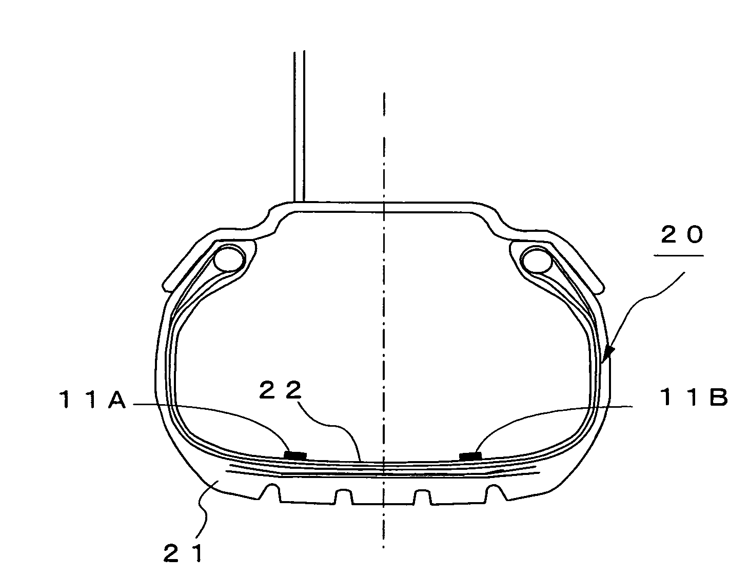
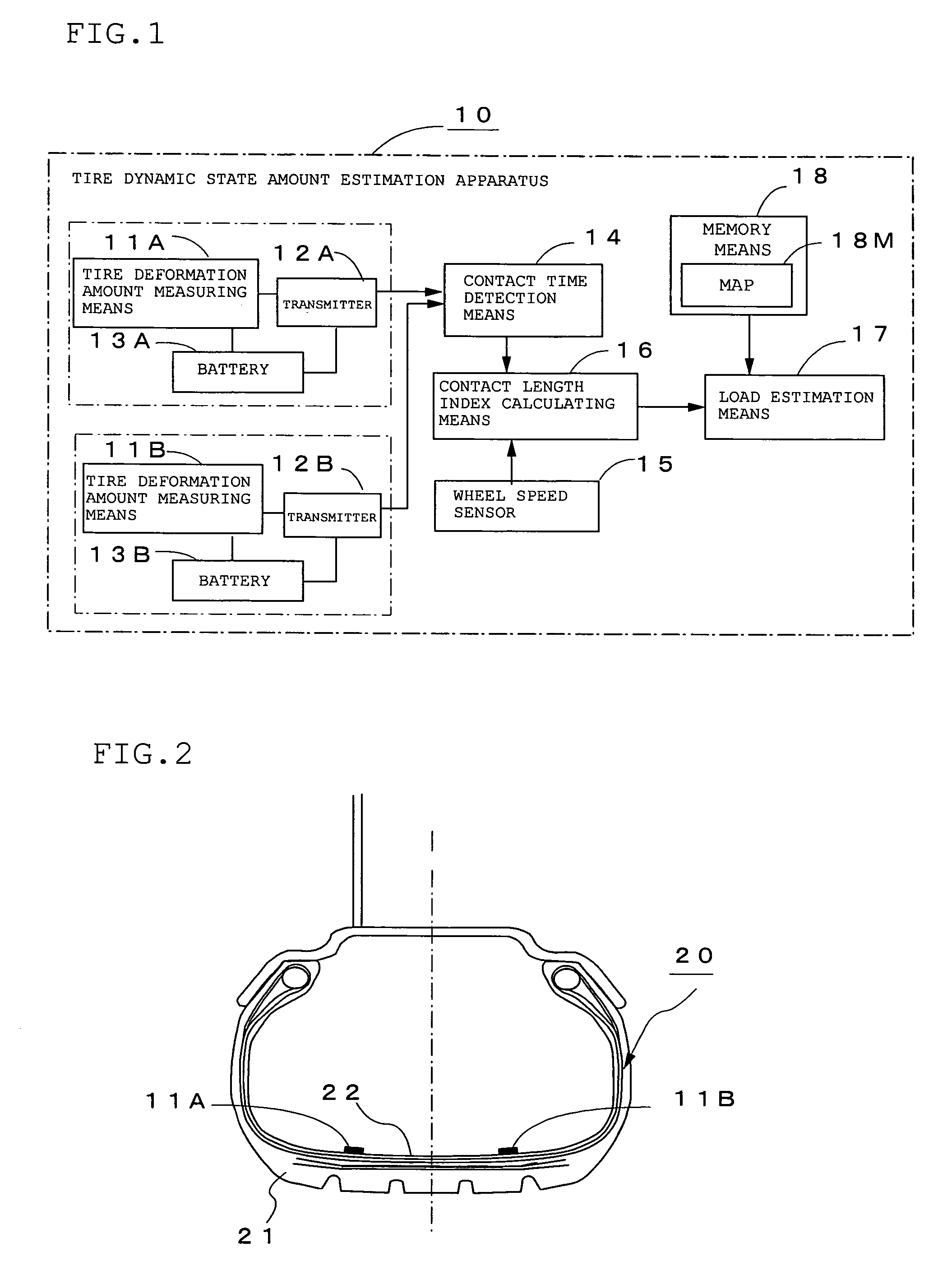
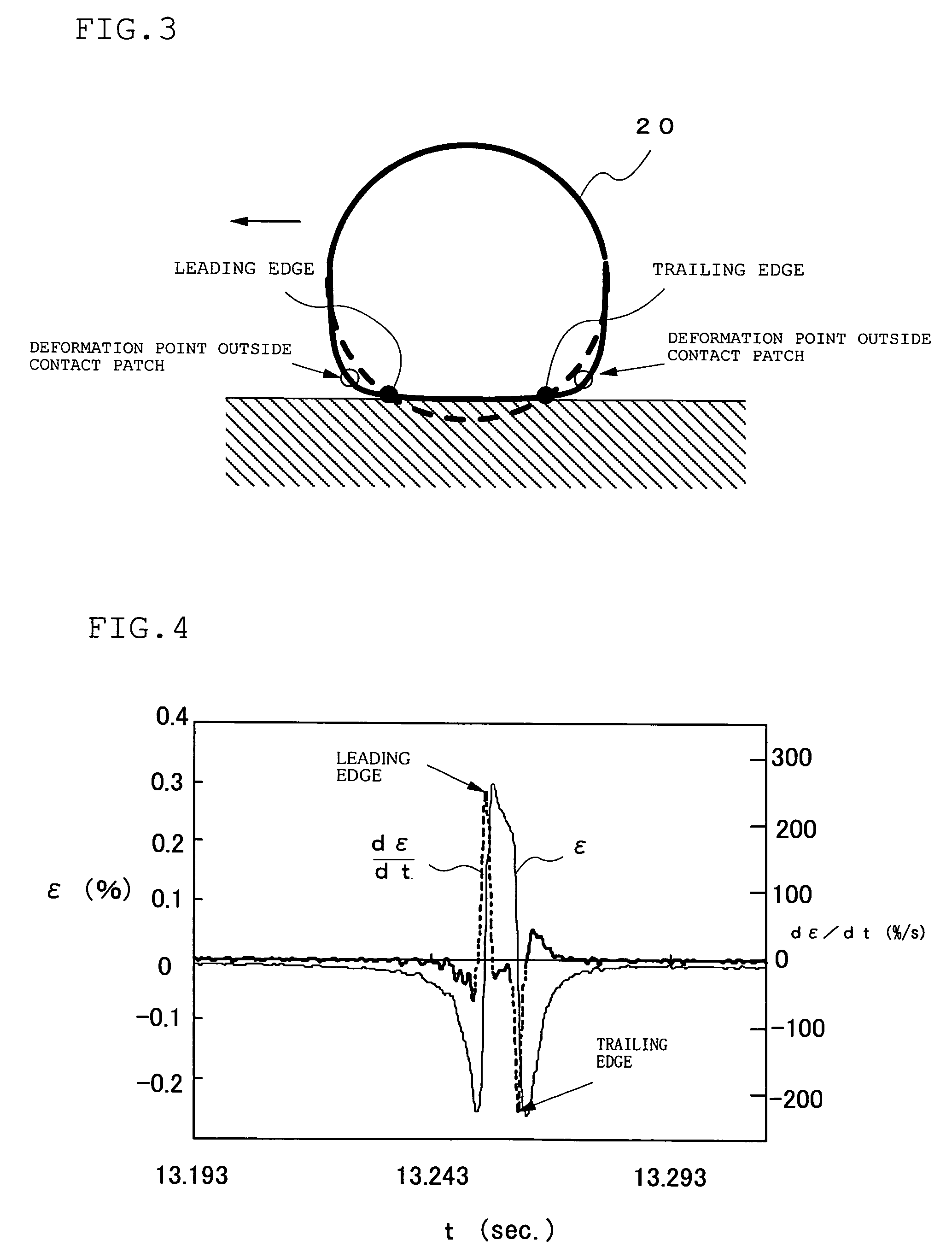
[0148]FIG. 1 is a functional block diagram showing the constitution of a tire dynamic state amount estimation apparatus 10 according to Embodiment 1 of the present invention, and FIG. 2 is a diagram of a tire 20 with sensors according to the present invention. In these figures, 11A and 11B denote tire deformation amount measuring means for measuring the deformation amount of an inner liner portion 22 which is deformed by an input into a tire tread 21 from the road surface, 12A and 12B transmitters for transmitting the measurement data of the above tire deformation amount measuring means 11A and 11B, 13A and 13B batteries for supplying power to the above tire deformation amount measuring means 11A and 11B and the above transmitters 12A and 12B, 14 contact time detection means for detecting the contact time during which the tire 20 with sensors is in contact with the road surface based on temporal in the deformation amount of the inner liner portion 22 which are the outputs of the abo...
embodiment 2
[0164]In the above Embodiment 1, strain in the circumferential direction at the positions which are axisymmetrical in the axial direction about the center in the axial direction of the tire of the inner liner portion 22, a change in strain in the circumferential direction, or bending strain outside the tread surface is measured to obtain the average value k of contact length indices kA and kB at the above two positions, and a load applied to the tire 20 with sensors is estimated from the average value k of contact length indices. Lateral force generated in the above tire can be estimated from the ratio R of the above contact length indices kA and kB at the above two positions.
[0165]That is, when lateral force is generated in the tire 20 with sensors, as shown in FIGS. 5(a) and 5(b), its contact shape becomes such that the contact length on one side of the center in the axial direction of the tire becomes large and the contact length on the other side becomes small. Then, when the co...
embodiment 3
[0190]Lateral force generated in the tire 20 with sensors is estimated from the ratio R of contact length indices and the ratio of the indices of deformation length outside the contact patch in the above Embodiment 2. It is possible to estimate longitudinal force generated in the above tire from the ratio Z of the indices of deformation length before and after the contact patch as will be described hereinafter.
[0191]The ratio Z of the indices of deformation length before and after the contact patch is obtained by calculating the lengths between the deformation points outside the contact patch shown by the white circles in FIG. 3 and the contact ends shown by the black circles on the front side of the contact patch (tread side) and the rear side of the contact patch (kick side). Since longitudinal force and the ratio of the indices of deformation length before and after the contact patch show a very good relationship as will be described hereinafter, a map showing the relationship be...
PUM
| Property | Measurement | Unit |
|---|---|---|
| length | aaaaa | aaaaa |
| volume resistivity | aaaaa | aaaaa |
| tan δ | aaaaa | aaaaa |
Abstract
Description
Claims
Application Information
 - R&D
- Intellectual Property
- Life Sciences
- Materials
- Tech Scout
- Unparalleled Data Quality
- Higher Quality Content
- 60% Fewer Hallucinations
Browse by: Latest US Patents, China's latest patents, Technical Efficacy Thesaurus, Application Domain, Technology Topic, Popular Technical Reports.
© 2025 PatSnap. All rights reserved.Legal|Privacy policy|Modern Slavery Act Transparency Statement|Sitemap|About US| Contact US: help@patsnap.com


