
Stereomicroscope or additional element for a stereomicroscope

a stereomicroscope and additional element technology, applied in the field of stereomicroscopes or additional elements of stereomicroscopes, can solve the problems of not being able to compensate, reducing the contrast reflection of fluorescent objects, and control cables that are not thought to be particularly reliabl

Active Publication Date: 2009-05-26
LEICA INSTR SINGAPORE PTE
View PDF14 Cites 31 Cited by
  • Summary
  • Abstract
  • Description
  • Claims
  • Application Information

AI Technical Summary

Benefits of technology

The solution results in a more robust, compact, and simpler stereomicroscope configuration that can be retrofitted, offering improved fluorescence imaging by reducing autofluorescence and maintaining parfocal and parcentric alignment, enhancing the microscope's reliability and usability.

Problems solved by technology

Moreover, control cables are components that are not thought to be particularly reliable so that, for example, optionally they must be readjusted or serviced.
This can be disadvantageous, because in this beam path autofluorescence phenomena can occur or such phenomena must be prevented by use of special measures.
In particular, the induced fluorescence illumination reduces the contrast reflection of the fluorescent object.
Although a second fluorescence excitation illumination is also provided, this illumination is directed onto the object as transmitted light illumination via a stand base of the microscope and is not available for incident light illumination.
The drawback of such a configuration is that it does not allow compensation for a misalignment when during binocular observation the object field is changed to an object field under stereoscopic observation.
To this extent, this prior art is less appropriate from a practical standpoint than is the solution according to the afore-said prior art with automatic compensation of a misalignment.
This known configuration provides no solution for observations in fluorescent light.
Although EP-B1-170857 thus also discloses a stereomicroscope with a switching device for a compound lens and a stereo lens on a stereomicroscope, a switching device is not provided with a gear and does not allow automatic compensation for misalignment.
Furthermore, this known configuration is not provided with a displaceable carrier.
In view of the lack of any means for compensating for misalignment and especially the lack of a displaceable carrier, it could therefore not be obvious to mount a binocular beam splitter between a carrier and a compound lens, for purposes of compensation.
Moreover, the use of structure as described in EP-B1-170857 would have resulted in loss of parcentricity so that a mere takeover of the known arrangement not could not be obvious but would not have led to the desired result of overcoming disadvantages in the prior art.
From this prior art, too, no teaching can be derived concerning an improvement over prior art patent publication US-A1-2002 / 0034001.
This system suppresses the disturbing autofluorescence, but does not provide a basis for selectively observing objects through a stereo lens or through a compound lens.

Method used


Image

  • Stereomicroscope or additional element for a stereomicroscope
  • Stereomicroscope or additional element for a stereomicroscope
  • Stereomicroscope or additional element for a stereomicroscope

Examples


Embodiment Construction

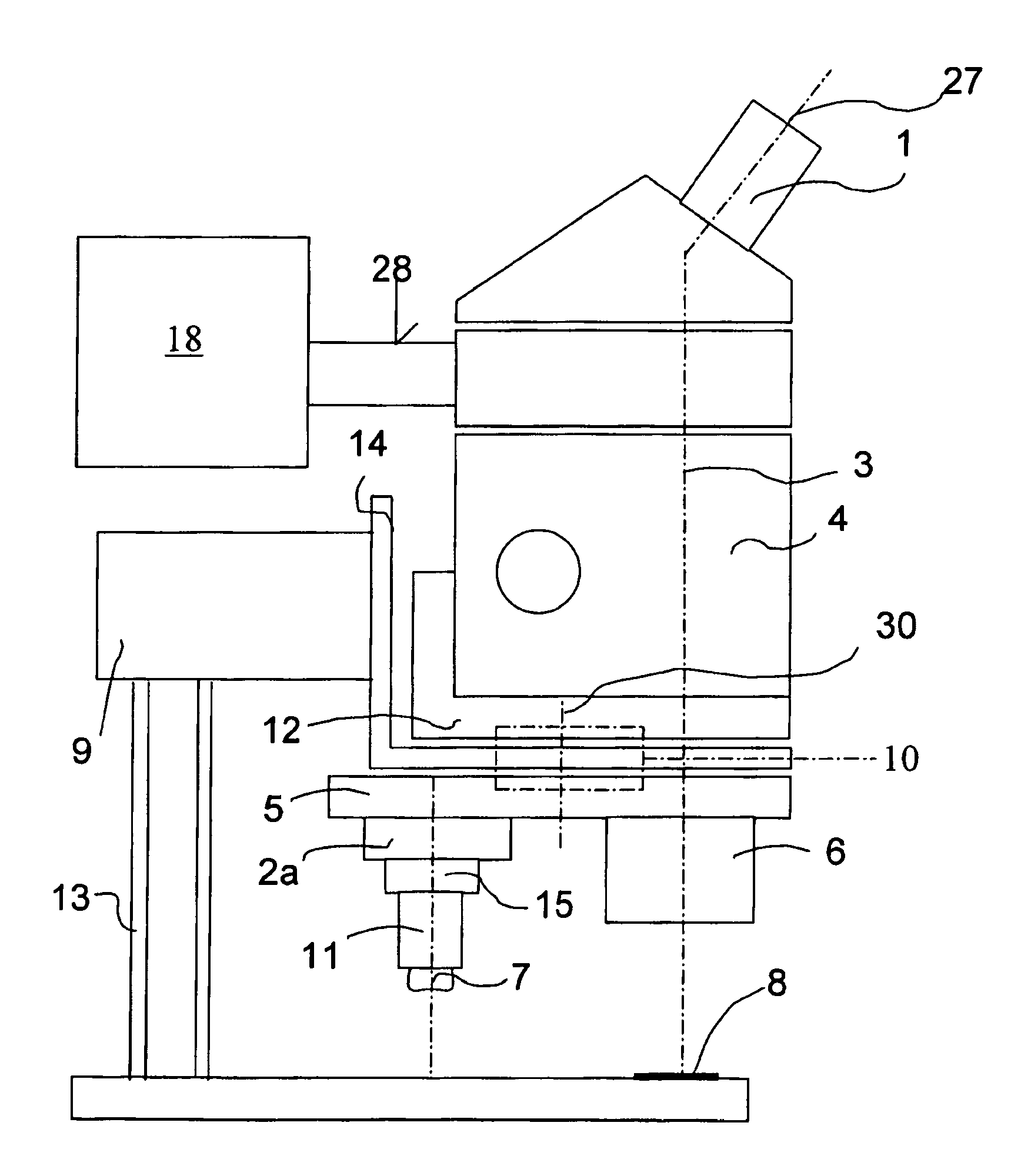
[0038]Refinements of the above described microscopes lead to further improved microscopes and, in particular, also provide solutions for the other objects. This main objective is also reached in the case of a microscope with incident illumination in that, while the switching system and the devices connected thereto are retained, the beam path for the illumination is also incorporated in integrated fashion.

[0039]In the sense of the invention, the terms used in this application can be explained as follows. By stereomicroscope is meant both a surgical microscope and a conventional stereomicroscope. By binocular tube is meant a conventional binocular tube as well as an assistant's binocular tube or a binocular connection to an image-uptaking device. A binocular beam splitter is a beam splitter that photo-optically combines the binocular observation beam paths with a single partial beam path of a stereoscopic microscope beam path and, for example, can be configured as a mirror or prism. ...


PUM


Abstract

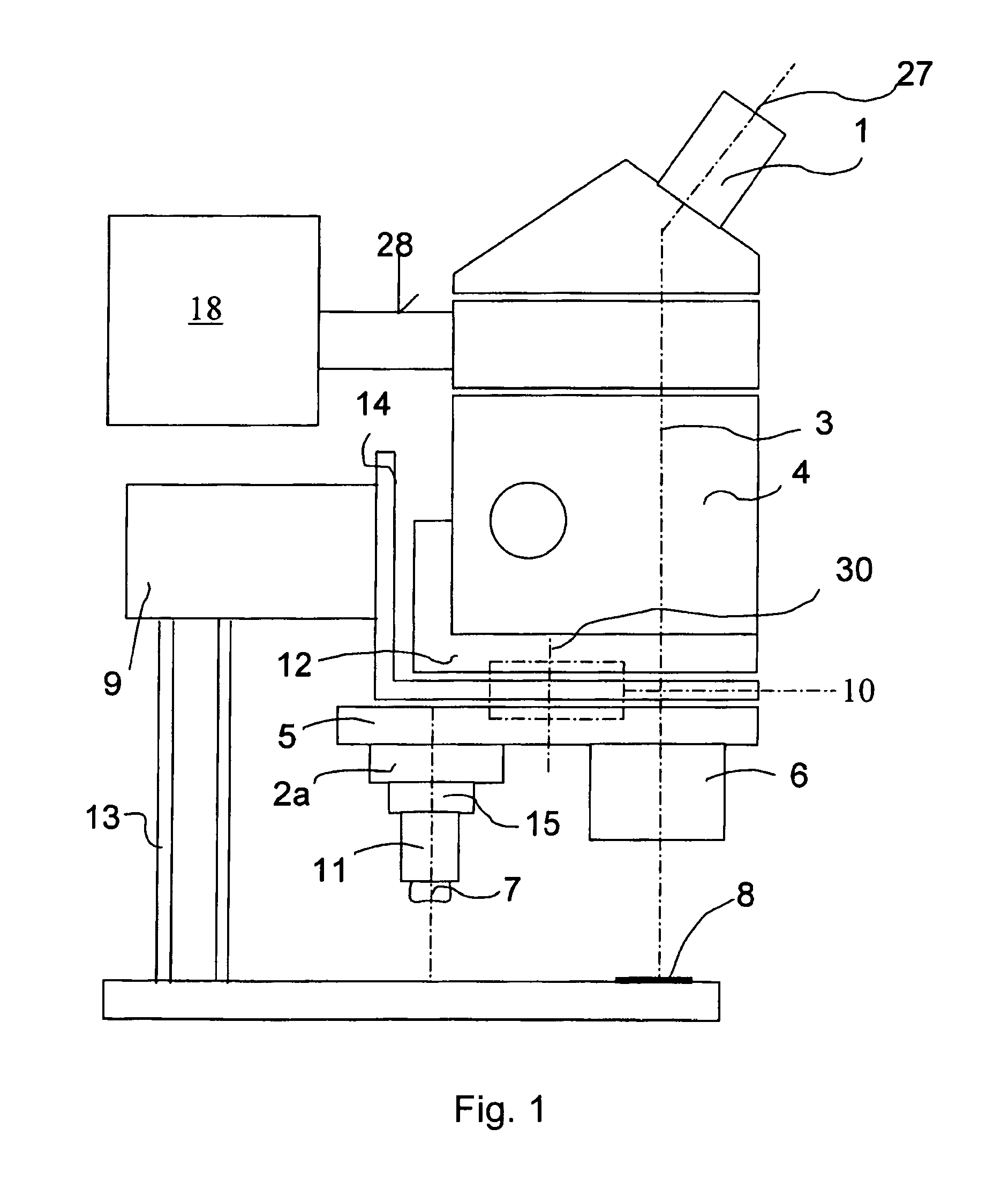
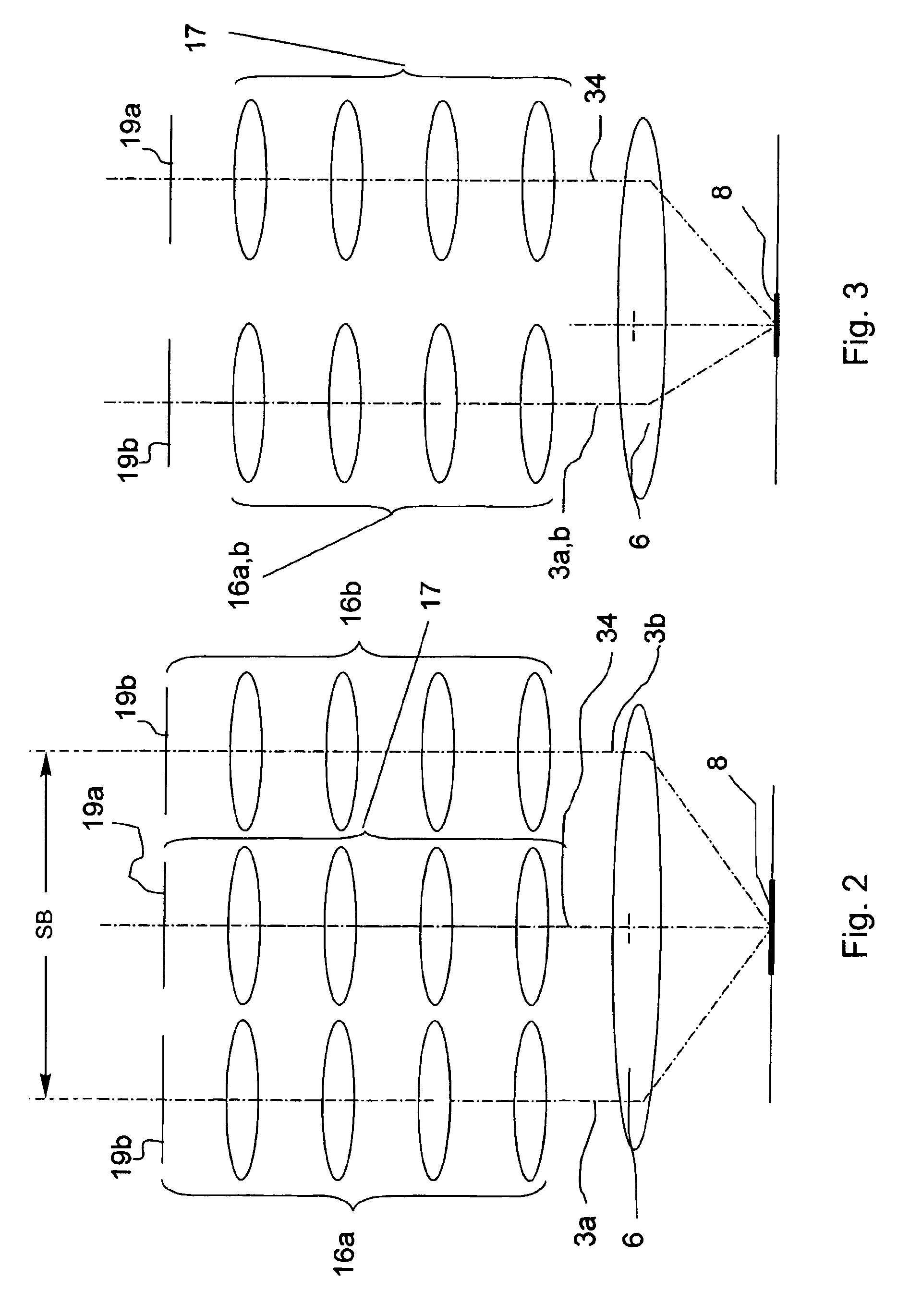
A stereomicroscope having a carrier (12) bearing a microscope body (4) displaceable obliquely relative to a displacement direction of a focus-adjusting mechanism (9). A binocular beam splitter (2a) is used to combine two stereoscopic observation beam paths (3a, 3b) into a common beam path (3c), wherein the axes of the two observation beam paths (3a, 3b) entering into the binocular beam splitter (2a) and the axis of the beam path (3c) emerging from the binocular beam splitter (2a) are parallel to each other, and the axis of the emerging beam path (3c) is disposed at displacement (Vs) from a symmetry axis of the two entering observation beam paths (3a, 3b). Displacement of the carrier being able to compensate for displacement (Vs). A switching device (5) is provided that can be activated to bring lenses (6, 7) over an object (8) parfocally and parcentrically.

Description

BACKGROUND OF THE INVENTION[0001]The invention relates to a stereomicroscope or to an additional element for a stereo-microscope with the ability to switch between different observation modes of which one is a stereoscopic observation mode through a stereo lens and the other a binocular monoscopic observation mode through a compound lens, the stereo lens and the compound lens being rotatably supported in a switching device in the stereoscopic beam path, and a prism arrangement being provided which during observation through the compound lens combines the two beam paths to form a single beam path.[0002]Such a stereomicroscope is described in US-A1-2002 / 0034001 published Mar. 21, 2002. This known stereomicroscope, in the direction of an observation beam path, includes a binocular tube and an automatic prism displacement mechanism with a binocular beam splitter that can be displaced by means of a control cable for the purpose of linking the binocular tube with either both stereoscopic ...

Claims


Application Information

Patent Timeline
Patent Type & Authority Patents(United States)
IPC IPC(8): G02B21/00G02B21/06G02B21/08G02B21/22
CPCG02B21/082G02B21/22
Inventor ZIMMERMAN, HEINZROTTERMAN, RUEDIBERTSCHI, PETER
Owner LEICA INSTR SINGAPORE PTE
Learn More