
Vector-matrix multiplication

Inactive Publication Date: 2009-05-19
LENSLET
View PDF51 Cites 34 Cited by
  • Summary
  • Abstract
  • Description
  • Claims
  • Application Information

AI Technical Summary

Benefits of technology

[0009]In some embodiments of the invention, the processor including the VMM core is a self-sufficient VMM processor, optionally provided as a single module, which includes at least one other processing unit that is adapted to perform operations that the VMM core is not optimally adapted to perform. The at least one other processing unit optionally includes a vector processing unit (VPU) and / or a scalar processing unit (e.g., a DSP). Potentially, such integration of a VMM core and at least one other processing unit allows a faster operation and / or reduces interference.
[0086]adapting values of at least one of said input vector on an input of said VMM and said matrix in a matrix portion of said VMM, in a manner that improves signal detection. Optionally, adapting comprising negating values of at least some vector elements. Alternatively or additionally, adapting comprises shifting a baseline value to be non-zero, such that light sources of the VMM are not extinguished to achieve this base line value. Alternatively or additionally, adapting comprises amplifying or reducing input value to make use of an available dynamic range of said VMM. Alternatively or additionally, adapting comprises shifting an input value base line to make use of an available dynamic range of said VMM. Alternatively or additionally, adapting comprises applying a linearity correction. Alternatively or additionally, adapting comprises weighting vector elements with weights that correspond to a number of zero values in a corresponding matrix column. Alternatively or additionally, adapting comprises weighting at least one of vector elements and matrix elements with weights that correspond to an average of values in corresponding matrix columns.

Problems solved by technology

As might be expected, however, even the fastest processors are not fast enough for the newest real-time applications that are conceived by system designers.
A typical optimization method is to not use available information to its fullest, thus conserving computing time and remaining within the limits of the hardware capabilities, trading off performance for quality.
However, even after such optimization, available processing power is not sufficient for the task and many of the protocols are not implemented in a complete manner (e.g., ignoring some available information and trading off performance for quality) or, alternatively the protocols are implemented on a multi-card device, with the users distributed between multiple costly cards.

Method used


Image

  • Vector-matrix multiplication
  • Vector-matrix multiplication
  • Vector-matrix multiplication

Examples


Embodiment Construction

SPE Overview

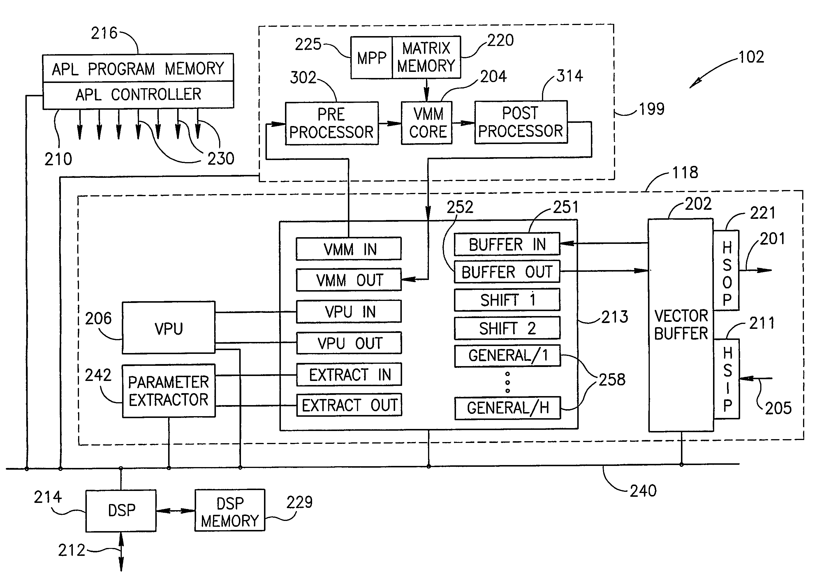
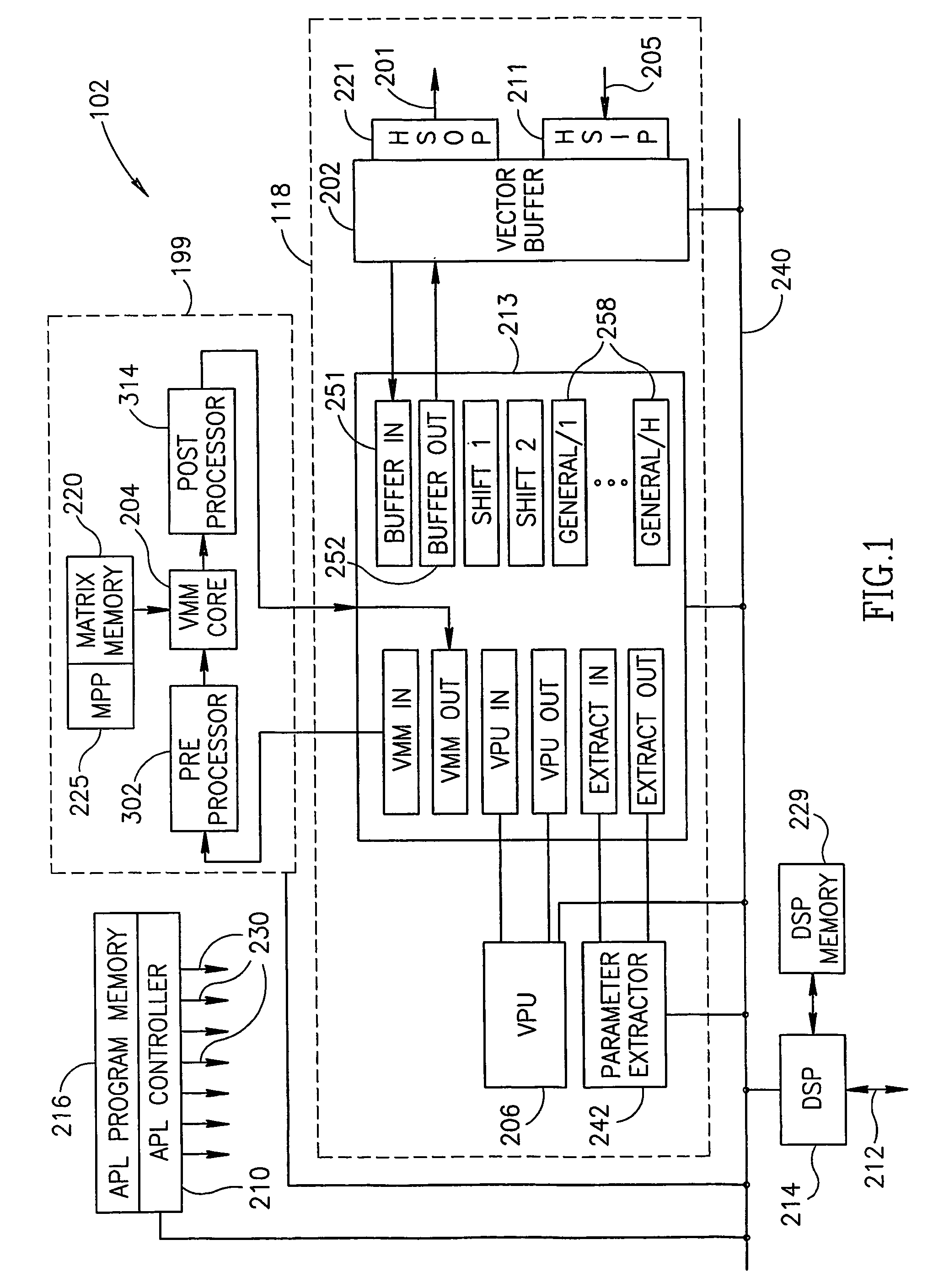
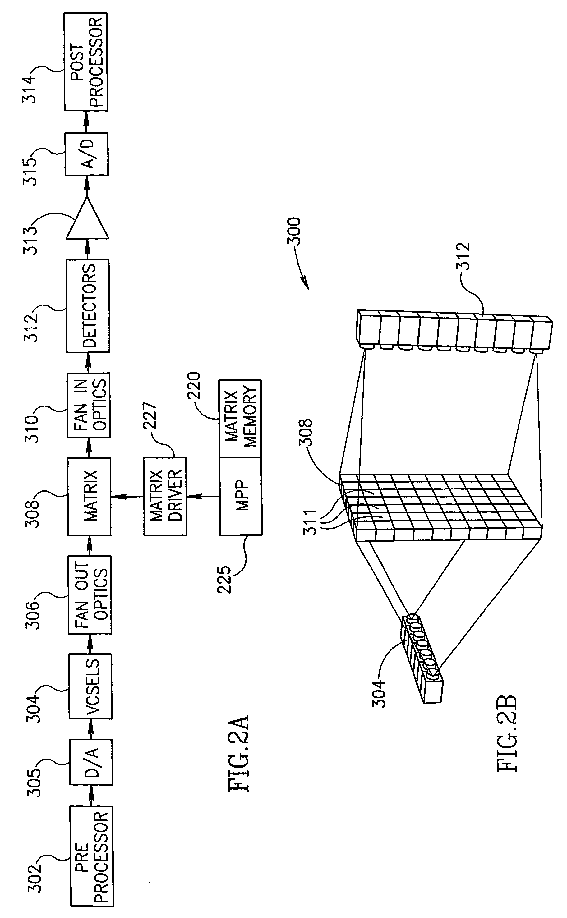
[0139]FIG. 1 is a schematic block diagram of a vector matrix multiplier (VMM) based signal processing engine (SPE) 102, in accordance with an exemplary embodiment of the invention. SPE 102 includes a VMM sub-system 199 adapted to perform vector matrix multiplication at a relatively high speed. Sub-system 199 includes a VMM core 204 which is adapted to perform multiplication of input vectors by a matrix at a relatively high rate. Optionally, VMM core 204 includes a programmable matrix, such that the matrix multiplying the input vectors may change according to the task performed and / or during the performance of a task (i.e., according to the steps of the task). In addition to VMM core 204, VMM sub-system 199 includes additional elements as is now described, which are used to translate between mathematical values and values processed internally by VMM core 204.

[0140]In some embodiments of the invention, for example as described below with reference to FIG. 2, matrix data of...


PUM


Abstract

An integrated VMM (vector-matrix multiplier) module, including an electro-optical VMM component that multiplies an input vector by a matrix to produce an output vector; and an electronic VPU (vector processing unit) that processes at least one of the input and output vectors. Various error reducing mechanisms are also discussed.

Description

RELATED APPLICATIONS[0001]The present application is a U.S. national application of PCT Application No. PCT / IL02 / 00727, filed Sep. 3, 2002, the disclosure of which is incorporated herein by reference.FIELD OF THE INVENTION[0002]The present invention is related to applications using vector matrix multiplication.BACKGROUND OF THE INVENTION[0003]In the quest for higher processing power, various hardware architectures have been proposed, including digital signal processors (DSPs), application specific integrated circuits (ASICs), field programmable gate arrays (FPGAs) and general CPUs. As might be expected, however, even the fastest processors are not fast enough for the newest real-time applications that are conceived by system designers. Typically, any algorithm used is optimized to take into account the characteristics of the particular hardware / software implementation. A typical optimization method is to not use available information to its fullest, thus conserving computing time an...

Claims


Application Information

Patent Timeline
IPC IPC(8): G06E3/00G06E1/04G06T1/00
CPCG06E1/045G06T1/0007
Inventor GOREN, AVNERSARIEL, AVIRAMLEVIT, SHIMONASAF, YOSEFALIBERMAN, SERGIOSENDER, BENZIONTZELNICK, TZVIHEFETZ, YARONMOSES, EYALMACHAL, VERED
Owner LENSLET
Learn More