Axial air-gap electronic motor

a technology of electronic motors and axial air gap, which is applied in the direction of heating types, magnetic circuit rotating parts, magnetic circuit shapes/forms/construction, etc., can solve the problems of wire connecting work and transition wire processing also require high labor and time, and achieve the effect of shortening the wire winding time of a core member and reducing the assembling manpower

Active Publication Date: 2009-05-12
FUJITSU GENERAL LTD
View PDF5 Cites 4 Cited by
  • Summary
  • Abstract
  • Description
  • Claims
  • Application Information

AI Technical Summary

Benefits of technology

[0007]The present invention has been made to solve the above-described problems, and accordingly an object thereof is to shorten the wire winding time of a core member and to reduce the assembling manpower in an axial air-gap electronic motor in which a stator is formed by a plurality of core members.
[0011]According to this feature, since the connecting means is provided on the outer periphery side and / or the inner periphery side of the flange portion, the core members can easily be connected to each other by merely causing the flange portions to face to each other.
[0015]According to this feature, by engaging the ribs formed in the flange portions with each other, not only the positioning of the core member can be performed easily but also the core member can be prevented from shifting in the rotation direction when the coil is wound.
[0017]According to this feature, by engaging the concave portion and the convex portion provided in the flange portions with each other in a male-female engagement manner, the core members can be positioned easily with respect to each other.
[0023]According to this feature, first, the core members are connected in a rod form in a row, and then the coil is wound from one core member toward the other core member and the core members are connected in a ring form. Thereby, not only the coil winding processing can be reduced but also the assembling manpower can be reduced.
[0029]According to this feature, since the coil is wound from one end side to the other end side of the connected core members at a time without being cut, the assembling step can be made high in speed and simple.

Problems solved by technology

However, in such a stator construction, since each core member, which has conventionally been in a separate state, is set on a wire winding device one by one so that a coil is wound thereon, the work for preparing core members necessary for assembling one stator requires much labor and time.
Also, after the coil has been wound on the core member, the coil pulled out of each core member for each phase must be connected, which presents a problem in that wire connecting work and transition wire processing also require much labor and time.

Method used


Image

  • Axial air-gap electronic motor
  • Axial air-gap electronic motor
  • Axial air-gap electronic motor

Examples


Embodiment Construction

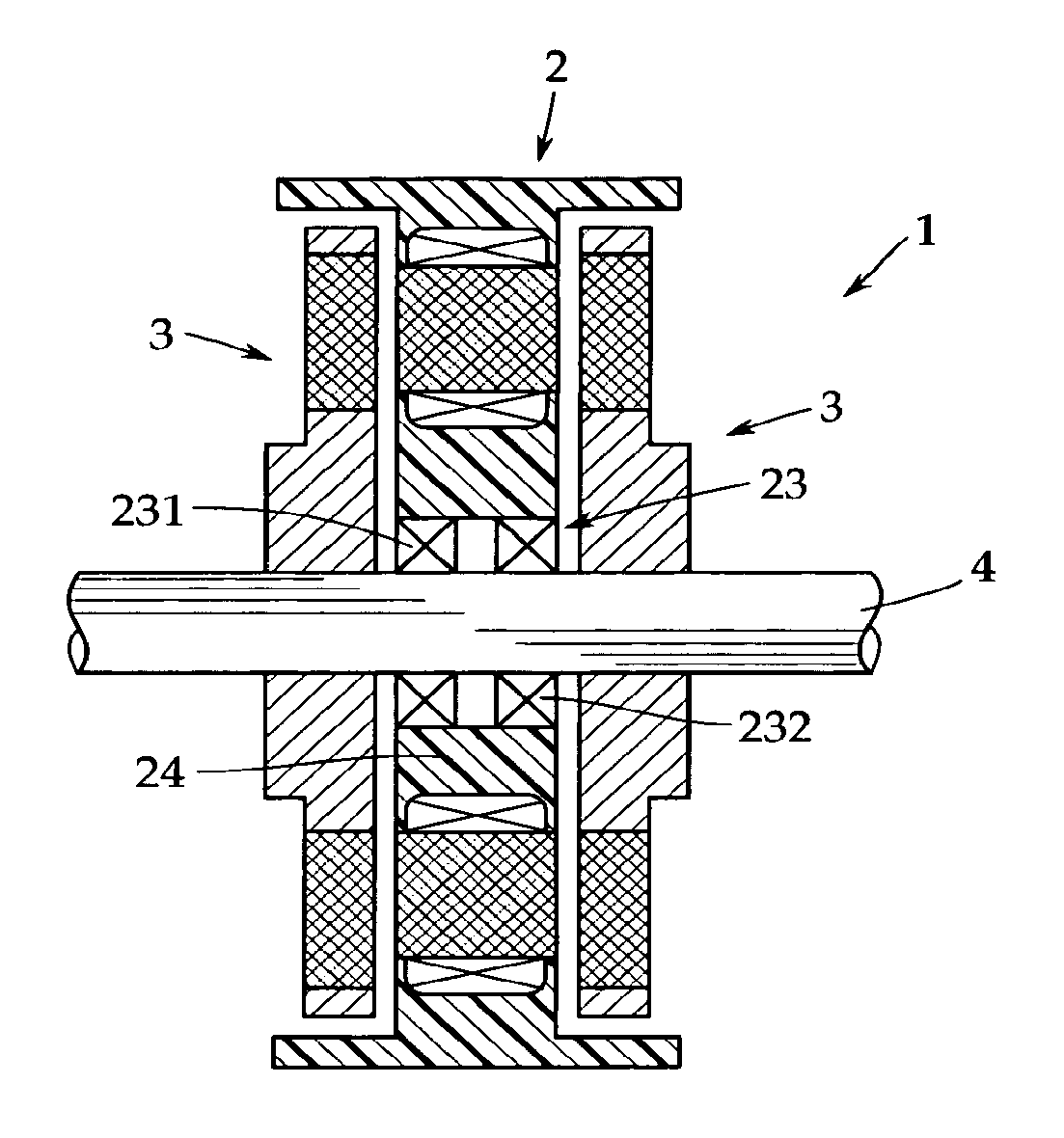
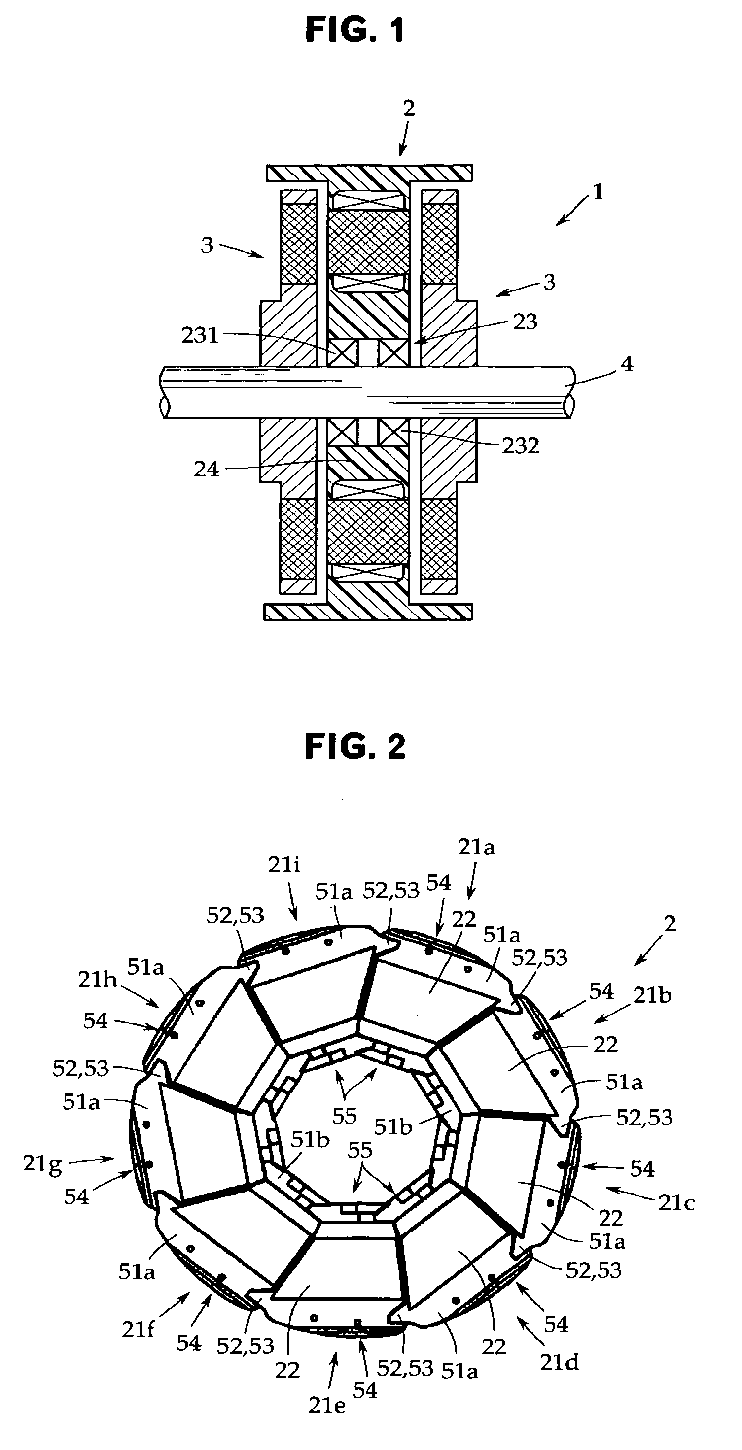
[0057]An embodiment of the present invention will now be described with reference to the accompanying drawings. The present invention is not limited to this embodiment. FIG. 1 is a sectional view schematically showing an internal construction of an axial air-gap electronic motor in accordance with one embodiment of the present invention, and FIG. 2 is a front view of a stator.

[0058]This axial air-gap electronic motor 1 includes a stator 2 formed into a disc shape and a pair of rotors 3 arranged opposedly on both side surfaces of the stator 2 with a predetermined gap being provided therebetween. Each of the rotors 3 is fixed coaxially to a rotor output shaft 4 that delivers a rotational driving force.

[0059]The stator 2 and the rotors 3 are housed in a bracket, not shown. In this example, the outer peripheral surface of the stator 2 is also used as the outer peripheral wall of the bracket, and a lid member, not shown, is installed at both ends thereof. The rotors 3 may be installed di...


PUM

PropertyMeasurementUnit
thicknessaaaaaaaaaa
magnetic fluxaaaaaaaaaa
timeaaaaaaaaaa

Abstract

In an axial air-gap electronic motor in which a teeth surface of a stator and a magnet surface of a rotor are arranged opposedly along the axis line direction of an output shaft of the rotor with a predetermined gap being provided therebetween, the stator has a plurality of core members connected in a ring form with the axis line being a center, and each of the core members is provided with a connecting device for connecting the teeth surfaces to each other in an opposed state. In order to shorten the wire winding time and reduce the assembling manpower for the core members, a stator is formed by connecting a plurality of core members in a ring form with the axis line being a center, and locking ribs are provided as connecting devices for connecting the core members to each other in a rod form along the axis line direction.

Description

TECHNICAL FIELD[0001]The present invention relates to an axial air-gap electronic motor. More particularly, it relates to a technique for assembling an axial air-gap electronic motor in which a stator is formed by a plurality of core members.BACKGROUND ART[0002]For example, as shown in Patent Document 1 (Japanese Patent Application Publication No. 2004-282989), an axial air-gap electronic motor is configured so that a rotor is arranged opposedly on one or both of side surfaces of a stator with a predetermined gap therebetween, and is characterized in that the thickness thereof in the rotating shaft direction can be reduced, namely, can be made flat as compared with a radial gap electronic motor of an inner rotor type etc.[0003]Also, since the facing area of the rotor and the stator and the winding occupying rate of a coil are improved, the magnetic flux is directed in the axial direction, so that high efficiency and high output can be achieved.[0004]The axial air-gap electronic moto...

Claims


Application Information

Patent Timeline
Patent Type & Authority Patents(United States)
IPC IPC(8): H02K1/18
CPCH02K1/148H02K1/182H02K15/095H02K29/03H02K21/24Y10T29/49012Y10T29/49009Y10T29/49071C12M23/44C12M37/00F24F8/10
Inventor KOJIMA, TOMONORITANNO, TOSHIAKITANAKA, YOSHIKAZUTANABE, YOICHIMATSUZAKI, HIROKAZUYAMADA, MASAKIMURAKAMI, MASANORI
Owner FUJITSU GENERAL LTD
Why Eureka
Try Eureka