
Constant-force rheometer

a constant force rheometer and rheometer technology, applied in the direction of direct flow property measurement, instruments, measurement devices, etc., can solve the problem of not providing an answer to the above question

Inactive Publication Date: 2009-05-05
THE UNIVERSITY OF AKRON
View PDF5 Cites 5 Cited by
  • Summary
  • Abstract
  • Description
  • Claims
  • Application Information

AI Technical Summary

Benefits of technology

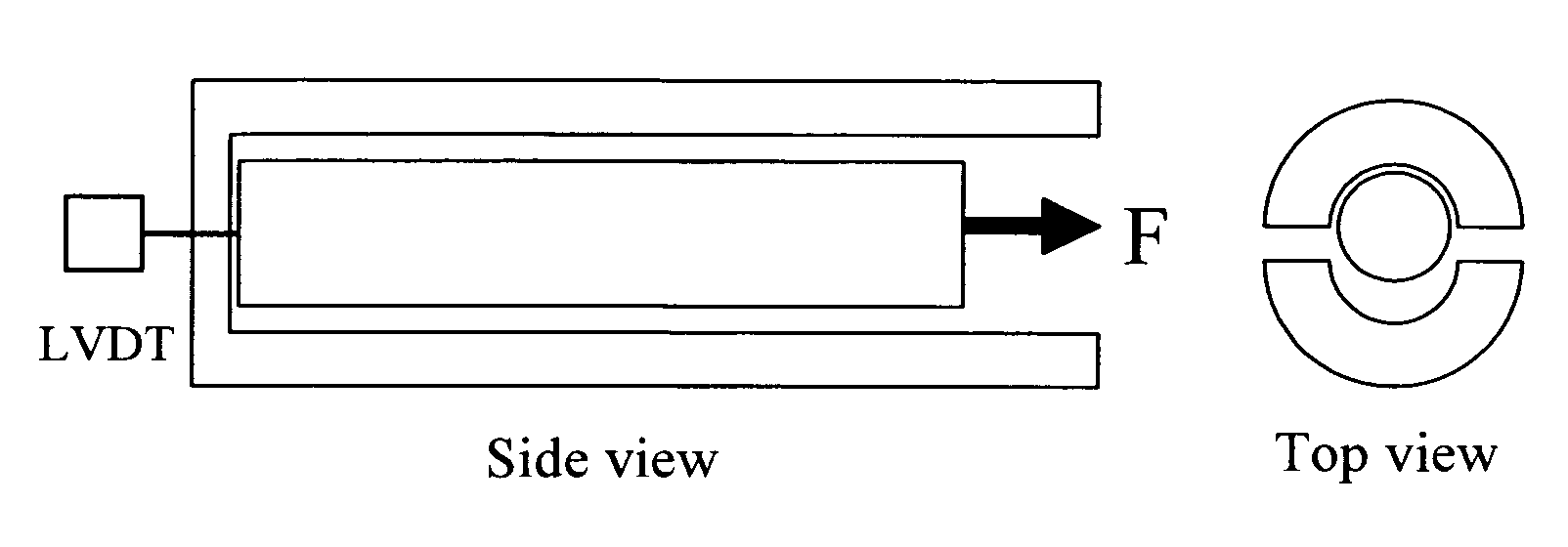
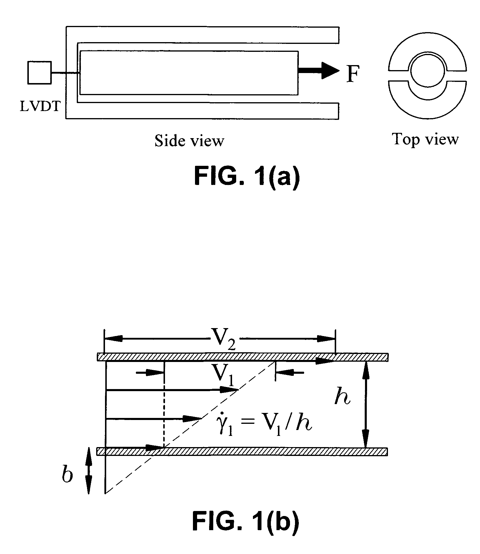
The present invention is about an improved constant-force shear rheometer that can measure the interfacial stick-slip transition in entangled polymer melts during simple shear. This is determined by the level of chain entanglement. The rheometer includes a tube with a piston and a means for maintaining the polymer sample in a molten state. The piston is driven with a known constant force and speed into the tube while the sample flows through the gap between the piston and the tube. The speed and position of the piston are recorded, and the force applied to the piston is also recorded. The invention also includes a process for making rheometric measurements of entangled polymer samples.

Problems solved by technology

Because all previous studies were based on sliding plate rheometry that operated in the displacement-controlled mode, they inherently could not provide an answer to the above question.

Method used


Image

  • Constant-force rheometer
  • Constant-force rheometer
  • Constant-force rheometer

Examples


Embodiment Construction

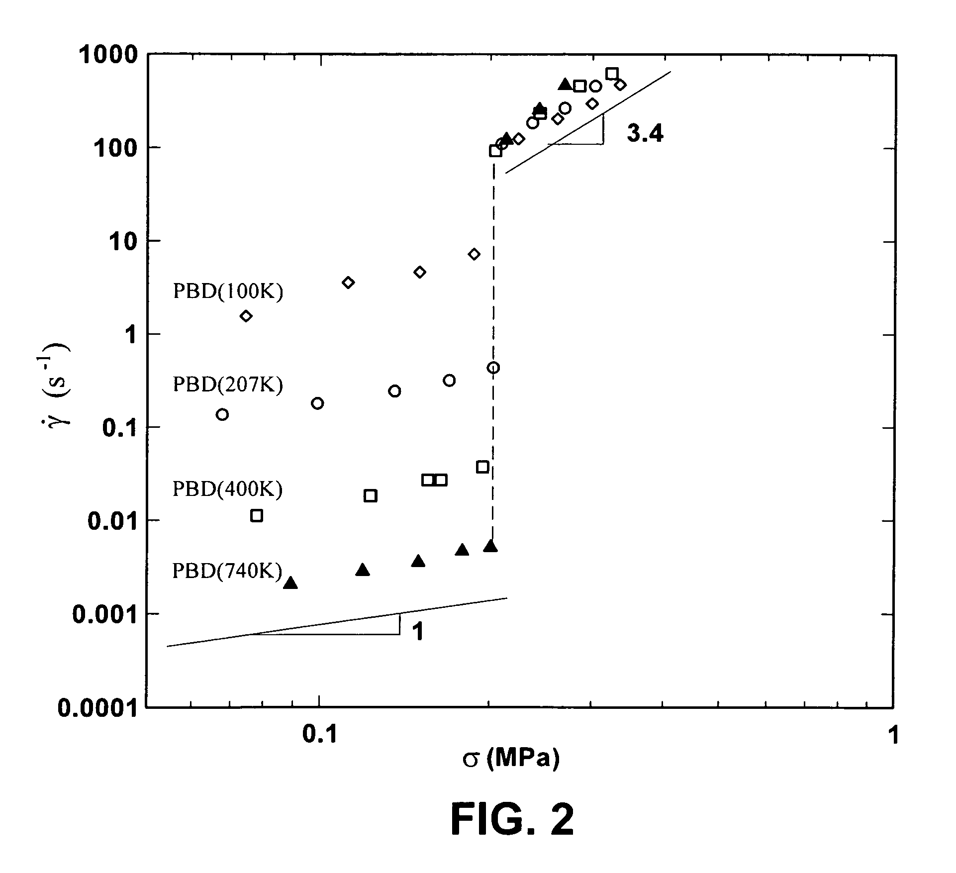
[0023]Some embodiments of the present invention relate to a constant-force piston shear Rheometer. Some embodiments are useful for taking rheometric measurements of samples that exhibit an interfacial stick-slip transition (SST). Some embodiments enable making such rheometric measurements of highly entangled polymer melt samples under simple shear conditions. The data obtained from these measurements can be dependent on molecular weight, chain structure and / or slip-surface conditions. According to some embodiments, the critical shear stress (i.e. the shear stress at which SST occurs) is a function of chemical structure. For example, some PBD samples exhibit a critical shear stress of about 0.2 MPa, while some PIP samples exhibit a critical shear stress of about 0.1 MPa.

[0024]Interfacial shear stress determines the nature of the hydrodynamic boundary condition (HBC) for entangled polymers on solid surfaces. Any violation of the no-slip boundary condition by a shearing apparatus opera...


PUM

PropertyMeasurementUnit
thickaaaaaaaaaa
gap distanceaaaaaaaaaa
diameteraaaaaaaaaa

Abstract

The present invention is generally directed to a method for measuring interfacial stick-slip transitions (SST) and an improved constant-force shear capable of measuring interfacial SST. Some embodiments are capable of measuring SST under simple shear conditions and / or in highly entangled polymer melts. Some embodiments include the application of a constant shearing force to a polymer sample.

Description

RELATED APPLICATION DATA[0001]This application claims priority from U.S. Provisional Patent Application No. 60 / 726,820, filed Oct. 14, 2005 and entitled “Improved Constant-Force Rheometer,” which is hereby incorporated by reference in its entirety.[0002]This work is supported, in part, by grants from the National Science Foundation (CTS-0115867 and 40596-AC7). The U.S. Government may have certain rights in this invention.BACKGROUND OF THE INVENTION[0003]The present invention is generally directed to a method for measuring interfacial stick-slip transitions (SST) and an improved constant-force shear capable of measuring interfacial SST. Some embodiments are capable of measuring SST under simple shear conditions and / or in highly entangled polymer melts. Some embodiments include the application of a constant shearing force to a polymer sample.[0004]Hydrodynamic boundary conditions (HBC) play a crucial role in characterization of flow behavior of various fluids. Since the time of Navier...

Claims


Application Information

Patent Timeline
Patent Type & Authority Patents(United States)
IPC IPC(8): G01N11/10
CPCG01N11/04G01N11/10G01N33/442G01N2011/0026
Inventor WANG, SHI-QING
Owner THE UNIVERSITY OF AKRON
Learn More