Systems and methods for use in detecting harmful aerosol particles
a technology of aerosol particles and detection systems, applied in the field of multi-spectral aerosol particle detection systems, can solve problems such as human harm from aerosol particles
- Summary
- Abstract
- Description
- Claims
- Application Information
AI Technical Summary
Benefits of technology
Problems solved by technology
Method used
Image
Examples
first embodiment
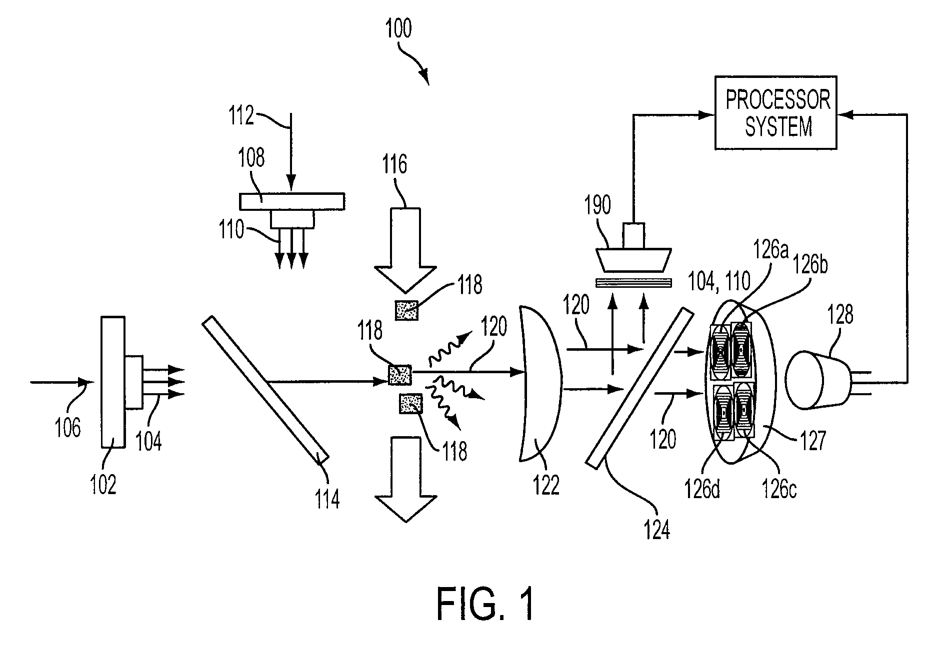
[0043]FIG. 1 is a schematic of a multi-spectral aerosol particle measurement system 100 according to the invention. As shown in FIG. 1, a multi-spectral aerosol particle measurement system 100 may include a long emitter 102 emitting long wavelength radiation 104 (e.g., UV light at approximately 340 nm) in a first direction 106 and a short emitter 108 emitting short wavelength radiation 110 (e.g., UV light at approximately 280 nm) in a second direction 112 (direction 112 may be orthogonal to direction 106 as illustrated in FIG. 1).
[0044]An emitter reflector 114 may be positioned at an intersection of first direction 106 and second direction 112 to pass long wavelength radiation 104 in first direction 106 and reflect short wavelength radiation 110 in first direction 106. In one embodiment, emitter reflector 114 is a filter, such as a dichroic filter, that is transparent to long wavelength radiation 104 and reflective to short wavelength radiation 110. In another embodiment, emitter re...
second embodiment
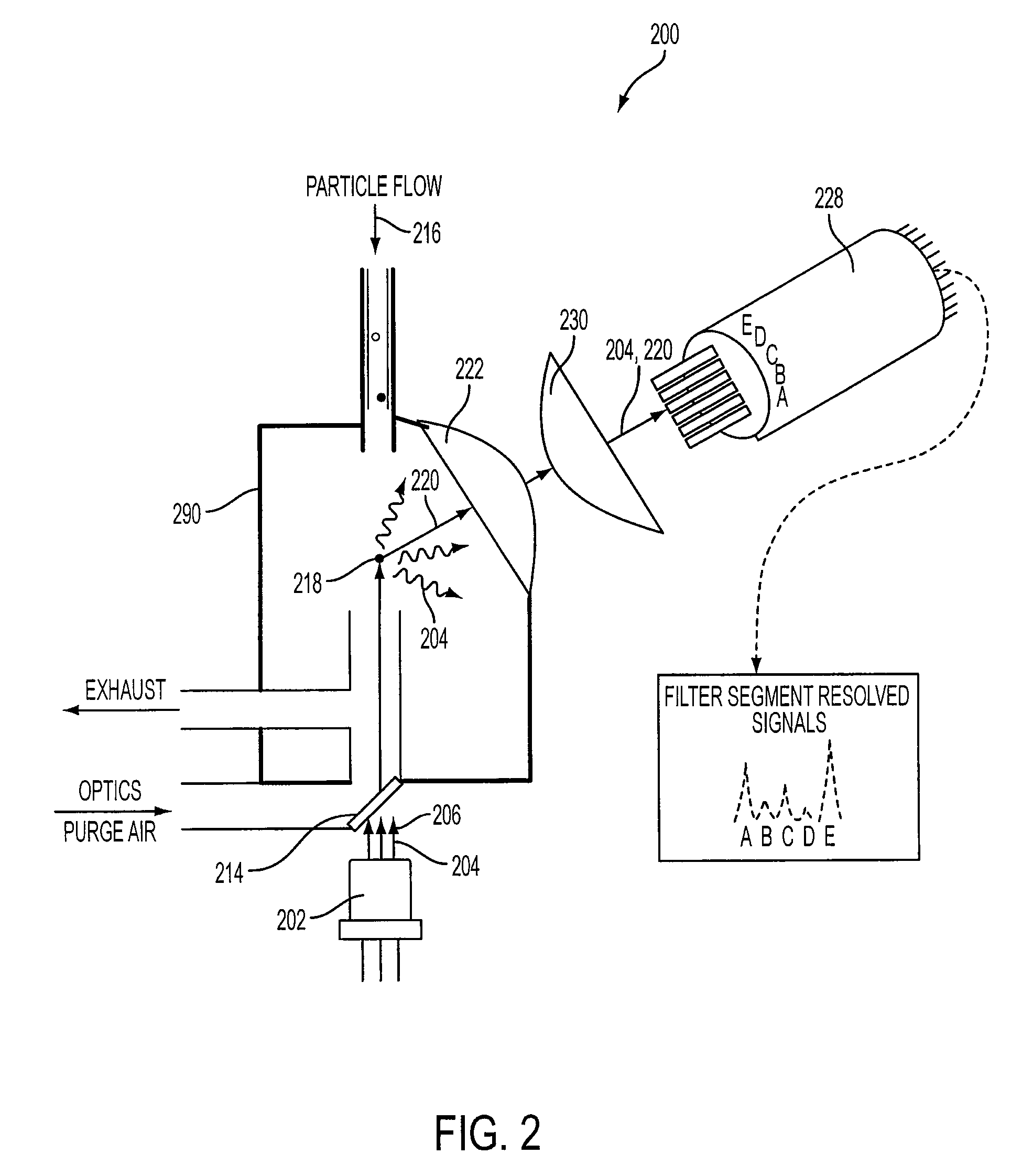
[0056]FIG. 2 is a schematic of a multi-spectral aerosol particle measurement system 200 according to the invention. As shown in FIG. 2, multi-spectral aerosol particle measurement system 200 may include a long emitter 202 emitting in a first direction 206 long wavelength radiation 204 (e.g., light having a wavelength of about 375 nm). A window 214, kept clean by a filtered purge air flow, allows radiation 204 to enter an optical chamber 290.
[0057]A fluid flow 216 containing particles (“particle stream 216”) may traverse first direction in a direction substantially opposite to that of long wavelength radiation 204. A particle 218 in stream 216 may produce fluorescent radiation 220 when exposed to radiation 204. An optical apparatus, which may include a collimating lens 222 and a focusing lens 230, may be positioned to receive and collimate fluorescent radiation 220, as well as long wavelength radiation 204 that has been scattered.
[0058]The focusing lens 230 may be positioned to recei...
third embodiment
[0064]FIG. 3 is a schematic of a multi-spectral aerosol particle measurement system 300 according to the invention. As shown in FIG. 3, multi-spectral aerosol particle measurement system 300 may include a long emitter 302 emitting in a first direction 306 long wavelength radiation 304 (e.g., light having a wavelength of about 405 nm) and a short emitter 308 emitting in a second direction 312 short wavelength radiation 310 (e.g., light having a wavelength of about 280 nm).
[0065]An emitter reflector 314 (e.g., a dichroic mirror) may be placed at an intersection of first direction 306 and second direction 312 to pass long wavelength radiation 304 in first direction 306 and reflect short wavelength radiation 310 in first direction 306. In one embodiment, emitter reflector 314 comprises a plurality of filters (not shown) that can be used to produce three or more different wavelength bands of radiation. Reflector 314 may be the same as reflector 124 described above.
[0066]A particle 318 in...
PUM
| Property | Measurement | Unit |
|---|---|---|
| first wavelength | aaaaa | aaaaa |
| wavelength | aaaaa | aaaaa |
| wavelength | aaaaa | aaaaa |
Abstract
Description
Claims
Application Information
 - R&D
- Intellectual Property
- Life Sciences
- Materials
- Tech Scout
- Unparalleled Data Quality
- Higher Quality Content
- 60% Fewer Hallucinations
Browse by: Latest US Patents, China's latest patents, Technical Efficacy Thesaurus, Application Domain, Technology Topic, Popular Technical Reports.
© 2025 PatSnap. All rights reserved.Legal|Privacy policy|Modern Slavery Act Transparency Statement|Sitemap|About US| Contact US: help@patsnap.com


