
Fringe field switching mode transflective LCD having slits in the reflective area of a pixel electrode that have an inclination angle greater than slits in the transmissive area by about 10 to 40 degrees

a transflective liquid crystal display and transflective technology, applied in non-linear optics, instruments, optics, etc., can solve the problems of inability to use reflective liquid crystal displays in dark places, inability to achieve the effect of reducing the power consumption of the transmissive liquid crystal display, and reducing the efficiency of the liquid crystal display, etc., to achieve wide viewing angles, high productivity, and high quality images

Active Publication Date: 2009-04-28
HYDIS TECH CO LTD
View PDF10 Cites 54 Cited by
  • Summary
  • Abstract
  • Description
  • Claims
  • Application Information

AI Technical Summary

Benefits of technology

The solution enables high-quality image display with wide viewing angles and improved electro-optical characteristics, facilitating manufacturing by matching V-R and V-T curves and reducing the step difference between transmissive and reflective areas, thus enhancing productivity.

Problems solved by technology

However, such a backlight unit may increase power consumption of the transmissive liquid crystal display.
However, the reflective liquid crystal display cannot be used in dark places.
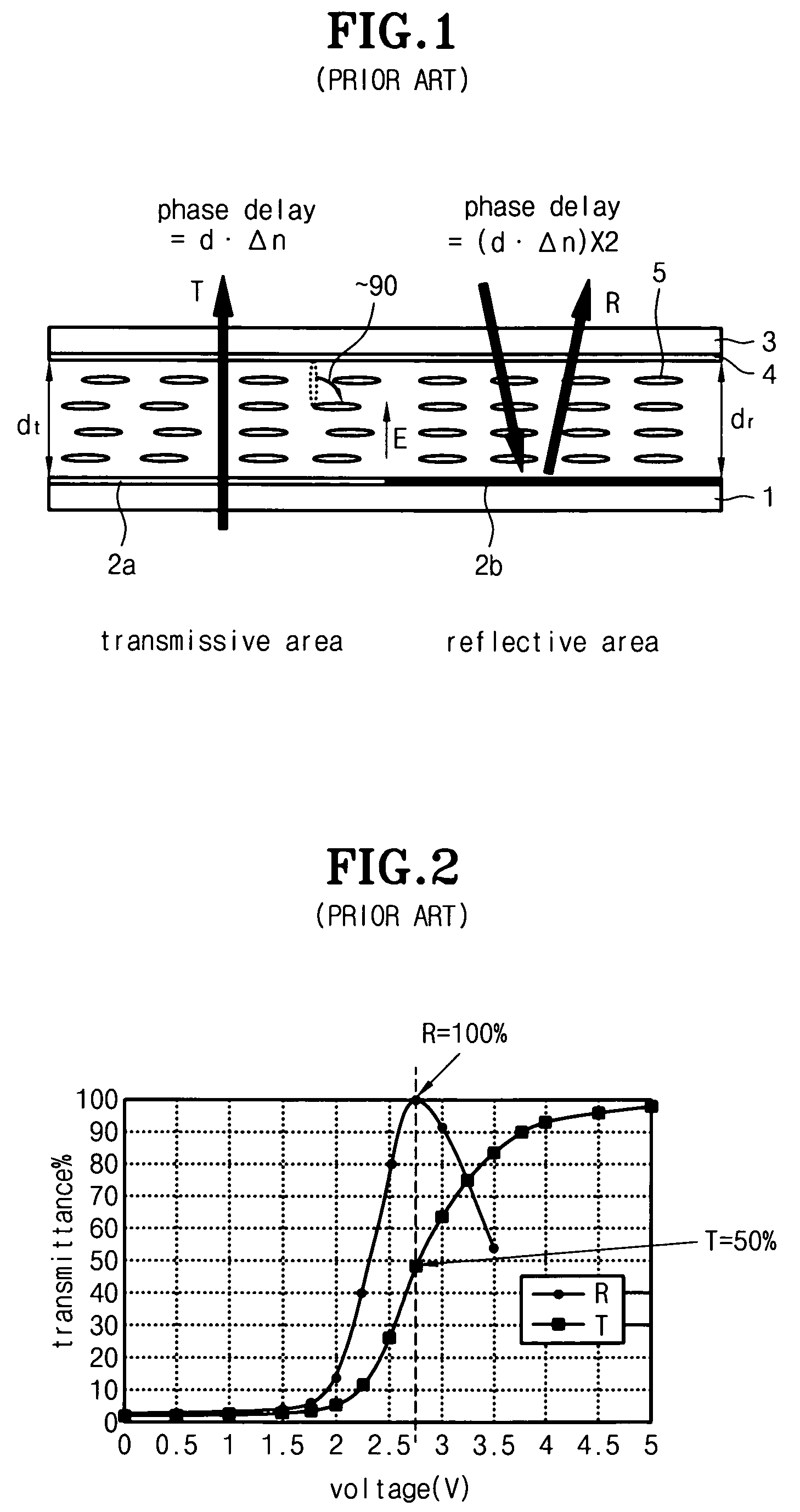
However, according to the conventional transflective liquid crystal display having the single cell gap structure as shown in FIG. 1, a phase delay (Δn·d) of the reflective area is twice larger than that of the transmissive area, so that a V-R curve in a reflective mode does not match with a V-T curve in a transmissive mode as shown in FIG. 2, thereby causing incorrect grayscales and inferior electro-optical characteristics of the liquid crystal display.
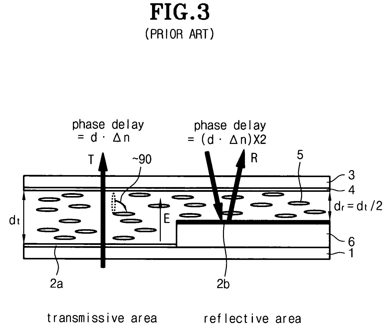
However, the conventional transflective liquid crystal display having the dual cell gap structure may present a great step difference, which is twice larger than that of the conventional transflective liquid crystal display having the single cell gap structure, due to a cell gap difference between the transmissive area and the reflective area, so the liquid crystal may be unevenly aligned.
For this reason, it is difficult to fabricate the conventional transflective liquid crystal display having the dual cell gap structure, so that productivity thereof may be lowered.
In addition, the liquid crystal adjacent to an alignment layer may be incompletely aligned as an electric field is applied thereto, thereby causing narrow viewing angles.

Method used


Image

  • Fringe field switching mode transflective LCD having slits in the reflective area of a pixel electrode that have an inclination angle greater than slits in the transmissive area by about 10 to 40 degrees
  • Fringe field switching mode transflective LCD having slits in the reflective area of a pixel electrode that have an inclination angle greater than slits in the transmissive area by about 10 to 40 degrees
  • Fringe field switching mode transflective LCD having slits in the reflective area of a pixel electrode that have an inclination angle greater than slits in the transmissive area by about 10 to 40 degrees

Examples


first embodiment

[0057]FIG. 5 is a sectional view illustrating an optical cell structure of a fringe field switching mode transflective liquid crystal display having a dual cell gap structure according to the present invention.

[0058]As shown in FIG. 5, the fringe field switching mode transflective liquid crystal display having the dual cell gap structure according to the first embodiment of the present invention includes a reflective area and a transmissive area, wherein an upper substrate 10 is aligned in opposition to a lower substrate 20 by interposing a liquid crystal layer 30 therebetween. An upper λ / 2 plate 11 and an upper polarizing plate 12 are sequentially aligned at an outer portion of the upper substrate 10. An organic insulation layer 21 and a reflective plate 22 are sequentially formed at an inner portion of the lower substrate 20 in opposition to the reflective area. In addition, a lower polarizing plate 24 is aligned at an outer portion of the lower substrate 20 and a lower λ / 2 plate ...

second embodiment

[0082]FIG. 16 is a view illustrating an optical cell structure of a fringe field switching mode transflective liquid crystal display having a single cell gap structure according to the present invention.

[0083]As shown in FIG. 16, the fringe field switching mode transflective liquid crystal display having the single cell gap structure according to the second embodiment of the present invention includes a reflective area and a transmissive area, wherein an upper substrate 160 is aligned in opposition to a lower substrate 100 by interposing a liquid crystal layer 150 therebetween. An upper polarizing plate 170 is aligned at an outer portion of the upper substrate 160. A reflective plate 120 is provided at an inner portion of the lower substrate 100 corresponding to the reflective area. An upper λ / 4 plate 130 is provided between the reflective plate 120 and the liquid crystal layer 150. In addition, a lower polarizing plate 110 is aligned at an outer portion of the lower substrate 100 a...


PUM

PropertyMeasurementUnit
angleaaaaaaaaaa
thicknessaaaaaaaaaa
heightaaaaaaaaaa

Abstract

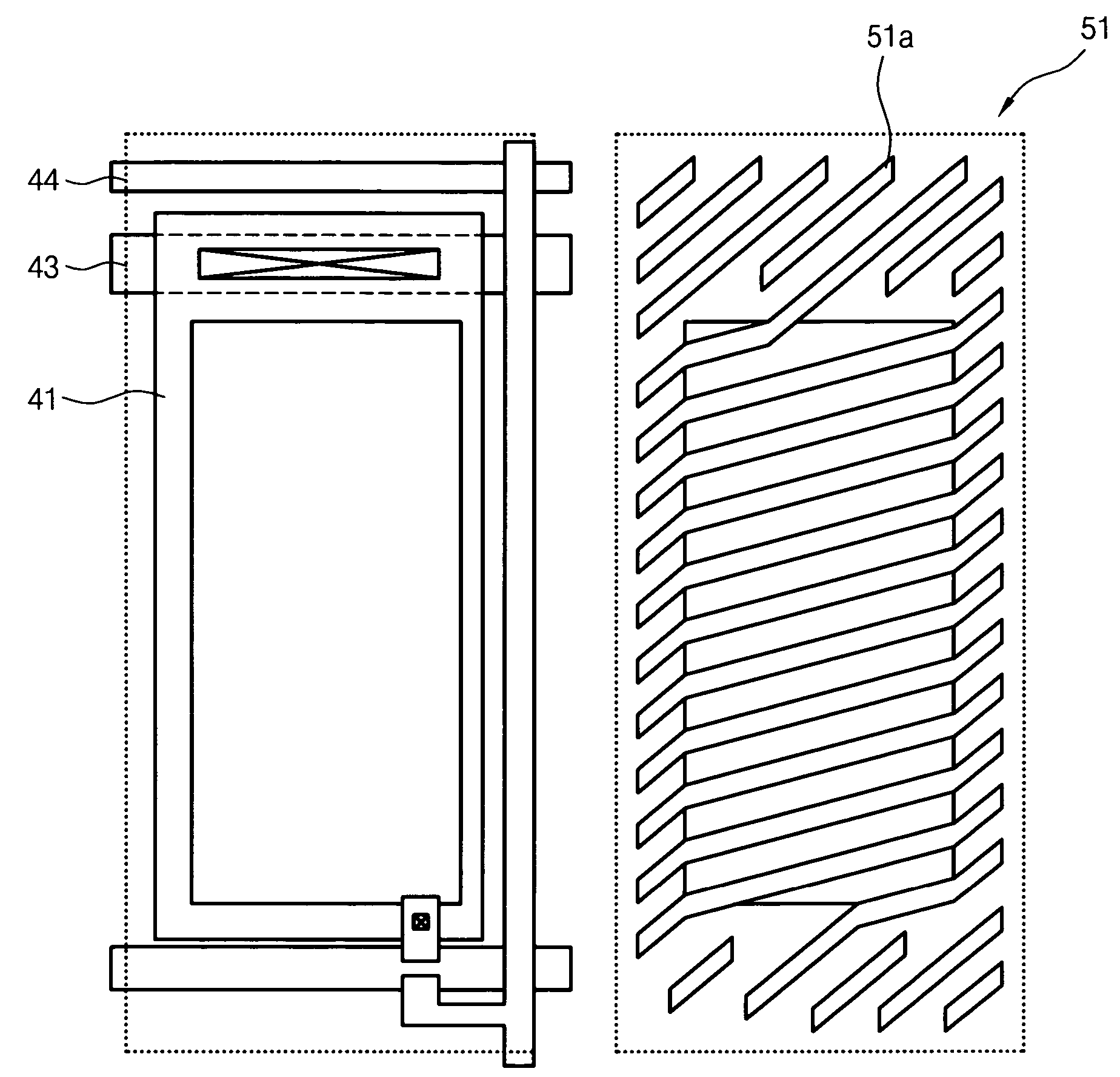
Disclosed is a fringe field switching mode transflective liquid crystal display capable of displaying high quality images. The transflective liquid crystal display includes a lower substrate having a counter electrode and a pixel electrode, an upper substrate aligned in opposition to the lower substrate by interposing a liquid crystal layer therebetween, an upper polarizing plate, a lower polarizing plate, a reflective plate provided at an inner portion of the lower substrate, a lower λ / 2 plate, and an upper λ / 2 plate. An inclination angle, a slit width and a slit interval of the pixel electrode of the reflective area are different from those of the pixel electrode of the transmissive area. The liquid crystal layer presents a phase delay of about 0 to λ / 4 in the reflective area and presents a phase delay of about 0 to λ / 2 in the transmissive area.

Description

BACKGROUND OF THE INVENTION[0001]1. Field of the Invention[0002]The present invention relates to a fringe field switching mode transflective liquid crystal display. More particularly, the present invention relates to a fringe field switching mode transflective liquid crystal display capable of displaying high quality images with wide viewing angles.[0003]2. Description of the Prior Art[0004]As generally known in the art, liquid crystal displays are classified into transmissive liquid crystal displays using backlight units as light sources thereof and reflective liquid crystal displays using natural light as light sources thereof. Since the transmissive liquid crystal display employs the backlight unit to generate light, it can display bright images in dark places. However, such a backlight unit may increase power consumption of the transmissive liquid crystal display. In contrast, the reflective liquid crystal display uses natural light as a light source without employing the backli...

Claims


Application Information

Patent Timeline
Patent Type & Authority Patents(United States)
IPC IPC(8): G02F1/1335
CPCG02F1/133555G02F1/134363G02F2001/133638G02F2201/122G02F1/133638G02F1/1335G02F1/1343
Inventor JEONG, YOUN HAKKIM, HYANG YULPARK, JUN BAEKKIM, KWI HYUN
Owner HYDIS TECH CO LTD
Learn More