
Method of correcting the output signal of an analog amplifier, amplifier module and measuring device

a technology of amplifier module and output signal, which is applied in the direction of differential amplifier, dc-amplifiers with dc-coupled stages, and amplifiers with semiconductor devices/discharge tubes, etc. it can solve the problems of excessive low-frequency noise in the entire circuit, dc voltage errors, thermo-voltage errors, etc., and achieve precise and fast amplifiers and large current consumption. , the effect of high precision

Active Publication Date: 2009-04-28
METTLER TOLEDO GMBH
View PDF10 Cites 4 Cited by
  • Summary
  • Abstract
  • Description
  • Claims
  • Application Information

AI Technical Summary

Benefits of technology

[0037]In a further exemplary embodiment, the timeout device consists of a switch which belongs to the signal-processing device and a timeout controller that is connected to the switch. Ideally, the switchover signals of the switchover controller are of a suitable nature to actuate the timeout controller, so that no additional elements are necessary for the detection of the switching jumps in the input signal.
[0045]In high-precision measuring devices, it has until now been necessary to use amplifiers that work with very high precision in order to meet the required accuracy. These precise and fast amplifiers are very expensive and consume a large amount of current. Using the disclosed exemplary methods offers a problem-free way to use very cost-effective and less precise amplifiers without compromising the accuracy of the measuring device. This is especially true in the case where a signal-processing unit has several amplifiers following each other in the circuit chain and where the errors of all of the amplifiers are eliminated by means of a single timeout means at the end of the amplifier chain.

Problems solved by technology

For cost reasons and for the sake of simplicity, one chooses in general a DC power supply for the measuring device and thus also a DC amplification although, due to the commonly known technical limitations, this choice often has disadvantages, specifically DC voltage errors such as thermo-voltage errors or voltage-offset errors in the analog amplifier as well as excessive low-frequency noise in the entire circuit.
With a non-switched differential amplifier, the 1 / f-noise which predominates at these low frequencies is superimposed on the measurement signal, whereby the quality of the amplified sensor signals is severely compromised.
In practical cases, however, the power density of white noise falls off at very high frequencies.
However, since analog amplifiers have only a limited bandwidth and rise time, their output signals cannot immediately follow the input signals.
The investigations have thus led to the conclusion that the speed of the transient decay, and therefore also the resultant error in amplitude, are variable.
Procedures of this kind add considerably to the cost and make the manufacturing process as well as the product more expensive.
These precise and fast amplifiers are very expensive and consume a large amount of current.

Method used


Image

  • Method of correcting the output signal of an analog amplifier, amplifier module and measuring device
  • Method of correcting the output signal of an analog amplifier, amplifier module and measuring device
  • Method of correcting the output signal of an analog amplifier, amplifier module and measuring device

Examples


Embodiment Construction

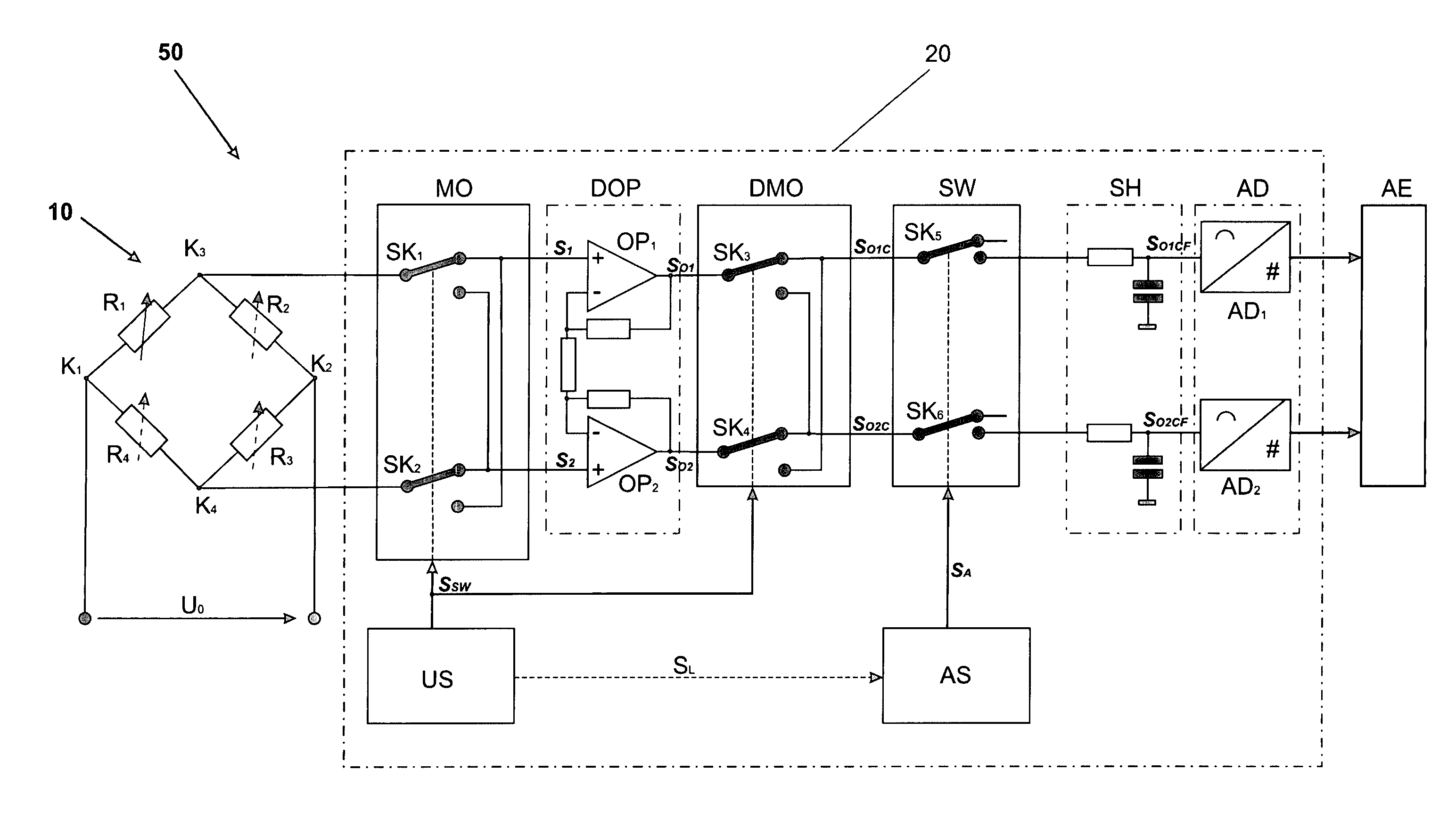
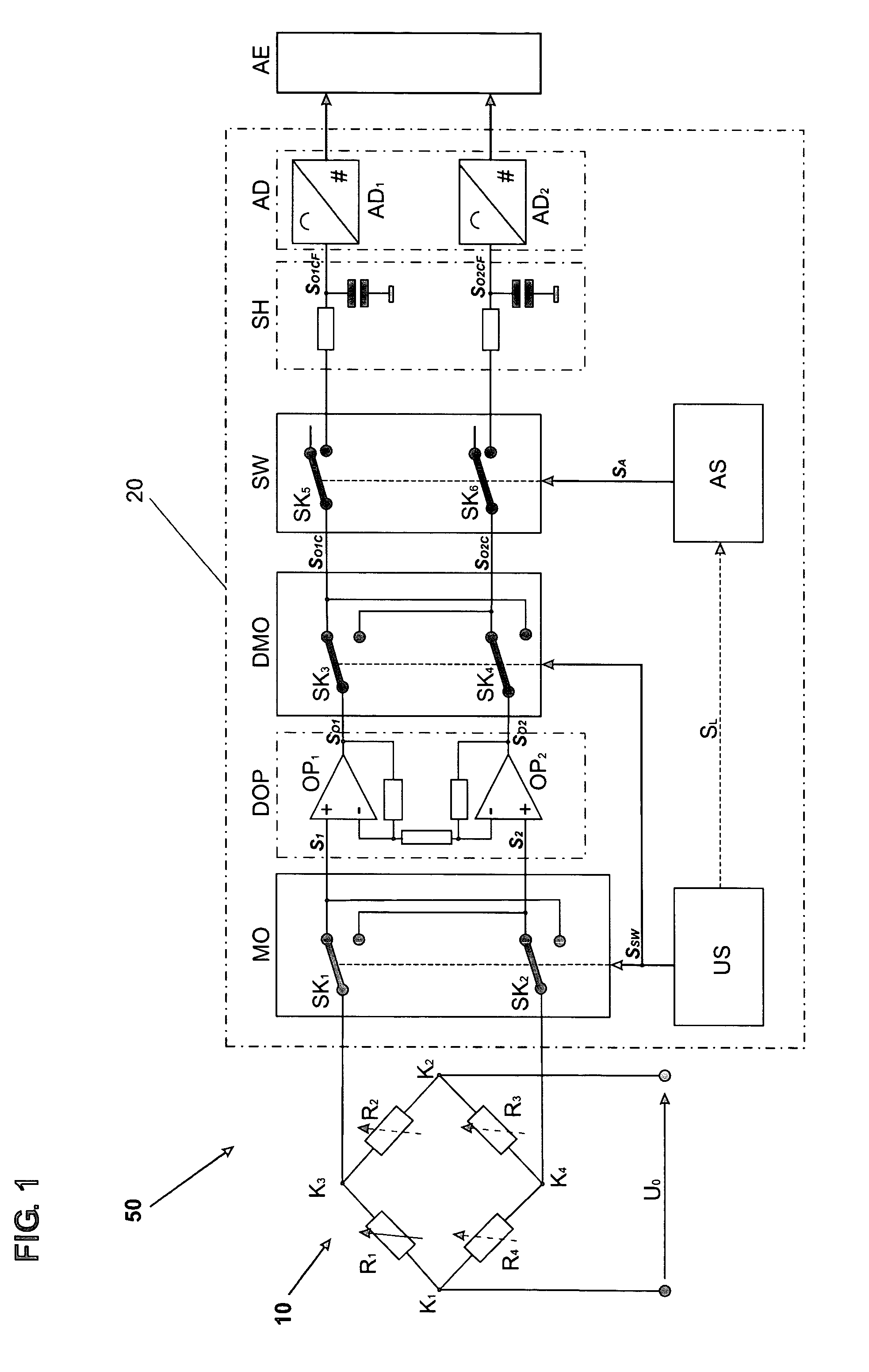
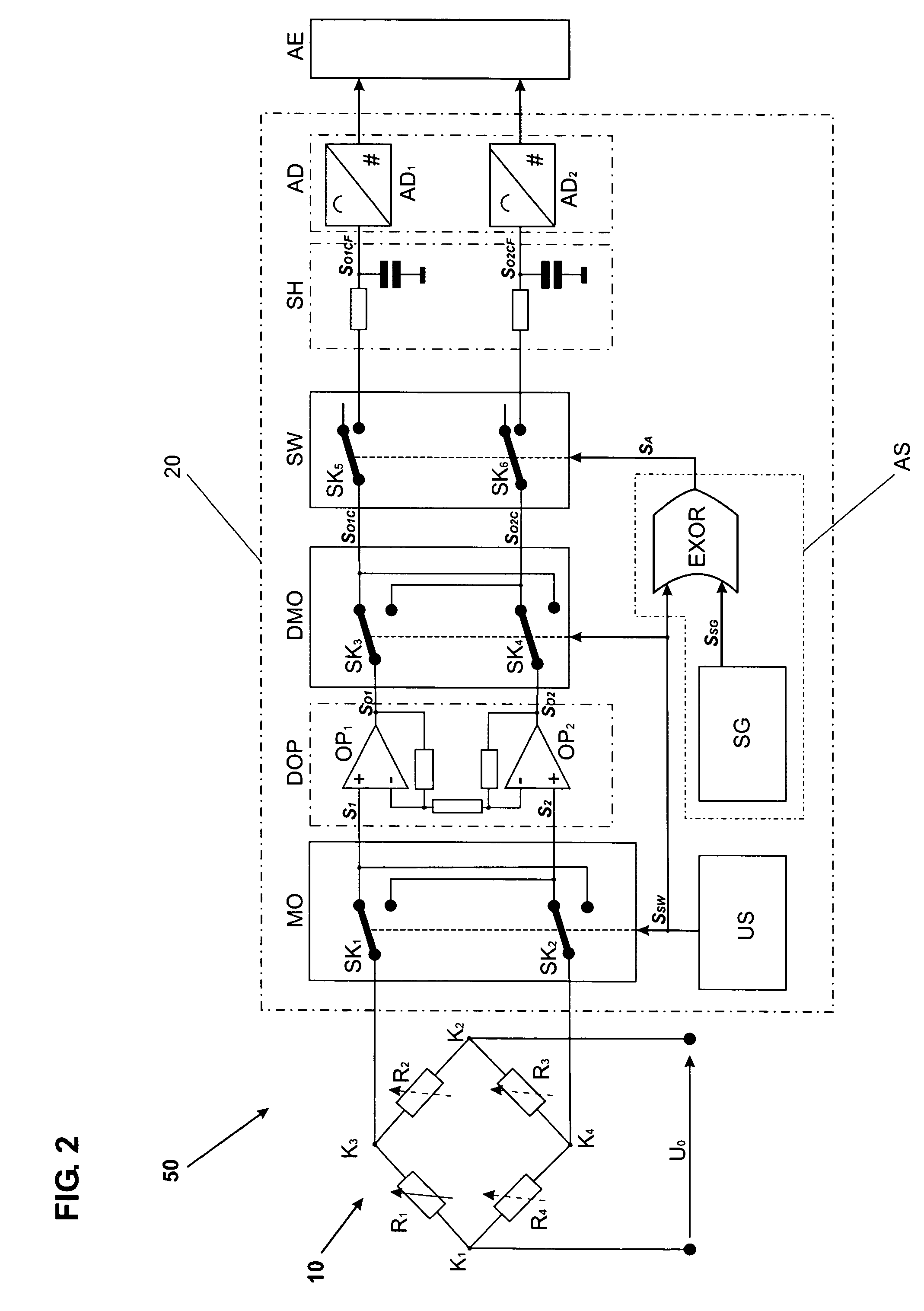
[0059]FIG. 1 gives a schematic representation of an exemplary measuring device 50 with a sensor 10 indicated in the form of a Wheatstone bridge circuit. The actual sensor element needs to be variable in the amount of its electrical resistance, so that the resistance value exhibits in the ideal case a linear dependence on the parameter to be measured or at least follows the latter according to a known systematic relationship. As is known, at least one of the four schematically represented resistors R1, R2, R3, R4 in a full-bridge circuit or at least one of the two resistors R1, R2 in a half-bridge is variable. The strain gauges of a force-measuring cell represent an example for this kind of a circuit arrangement. An operating voltage UO is applied to the nodes K1 and K2 of the Wheatstone bridge circuit. The two nodes K3 and K4 are connected to a signal-processing unit 20 which contains different processing stages MO, DOP, DMO, SW, SH, AD, AE which are connected so that they follow ea...


PUM


Abstract

A method is disclosed for correcting transfer errors of an analog amplifier that occur following a jump in the amplifier input signal caused by switching. A measuring device includes at least one sensor as well as a signal-processing unit connected to the sensor and analog amplifier. The signal-processing unit includes at least one modulator and / or a multiplexer, an analog amplifier and at least one processing stage following the analog amplifier in the circuit chain. The processing stage, dependent on the point in time when the switching jump occurs, is separated from the latter during a predetermined timeout phase duration by means of a switch that is arranged between the analog amplifier and the processing stage and is controlled by a timeout controller, and / or dependent on the point in time when the switching jump occurs, said processing stage is blocked by a timeout controller during a predetermined timeout phase duration.

Description

CROSS REFERENCE TO RELATED APPLICATIONS[0001]This application claims priority under 35 U.S.C. §119 to U.S. Provisional Application 60 / 751,636 filed in the U.S. Patent and Trademark Office on Dec. 20, 2005, the entire contents of which are hereby incorporated by reference in their entireties.FIELD[0002]A method, an amplifier module and a measuring device are disclosed, wherein a signal is amplified in a signal-processing unit, converted and transmitted to an output device.BACKGROUND INFORMATION[0003]Analog amplifiers, in particular operational amplifiers and differential amplifiers are used in signal-processing units in which an output signal of, e.g. a temperature-, humidity-, force-, or pressure sensor is transformed and processed. In most cases, sensors and signal-processing units are combined into so-called measuring devices and are used in industrial environments. An important group of measuring devices which impose very stringent requirements on a signal-processing unit are the...

Claims


Application Information

Patent Timeline
Patent Type & Authority Patents(United States)
IPC IPC(8): H03F1/02
CPCH03F3/387H03F3/45475H03F2200/261H03F2203/45138
Inventor BUCHER, CYRILLREBER, DANIELOUELLETTE, PHILIP R.
Owner METTLER TOLEDO GMBH
Learn More