
Surge arrester

a technology of surge arrester and resistor, which is applied in the direction of overvoltage protection resistor, emergency protective arrangement for limiting excess voltage/current, and arrangement responsive to excess voltage, etc., which can solve the problems of increasing the cost, deteriorating the short-circuit performance, and not being suitable for the casing to be made of a material

Active Publication Date: 2009-04-21
HITACHI ENERGY LTD
View PDF9 Cites 7 Cited by
  • Summary
  • Abstract
  • Description
  • Claims
  • Application Information

AI Technical Summary

Benefits of technology

[0012]It is a second object of the present invention to provide a surge arrester that can be manufactured with less variation of performance than hitherto known arresters.
[0013]It is a main object of the invention to provide a surge arrester that has improved short-circuit performance, that has smaller volume, and that may be manufactured in a more economic manner than according to the prior art.SUMMARY OF THE INVENTION
[0022]Further, the asymmetrical cross section of the loops may be adapted to shorten the free span for the rings or bands inside the loops and / or be adapted to enable the rings or bands to be wound closer to the stack.

Problems solved by technology

For this reason, it is not suitable for the casing to be made of a material that may be fragmented at an internal pressure increase, but instead to be made of rubber or a similar material.
If the rings are too far away from the varistor stack, the volume of the insulant has to be increased, which, of course, increases the cost, but above all it deteriorates the short-circuit performance because the rubber, or corresponding material, inside the rings prevents the arrester from ventilating and a higher pressure is built up.
This results in a much more violent short-circuit behaviour.
There is a considerable risk that the “belly” reaches the stack unless winding is performed with a decreasing tensile stress.

Method used


Image

  • Surge arrester
  • Surge arrester
  • Surge arrester

Examples


Embodiment Construction

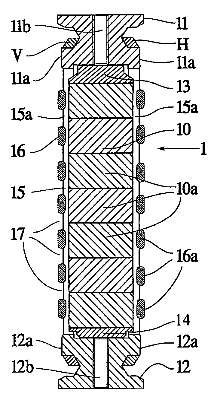
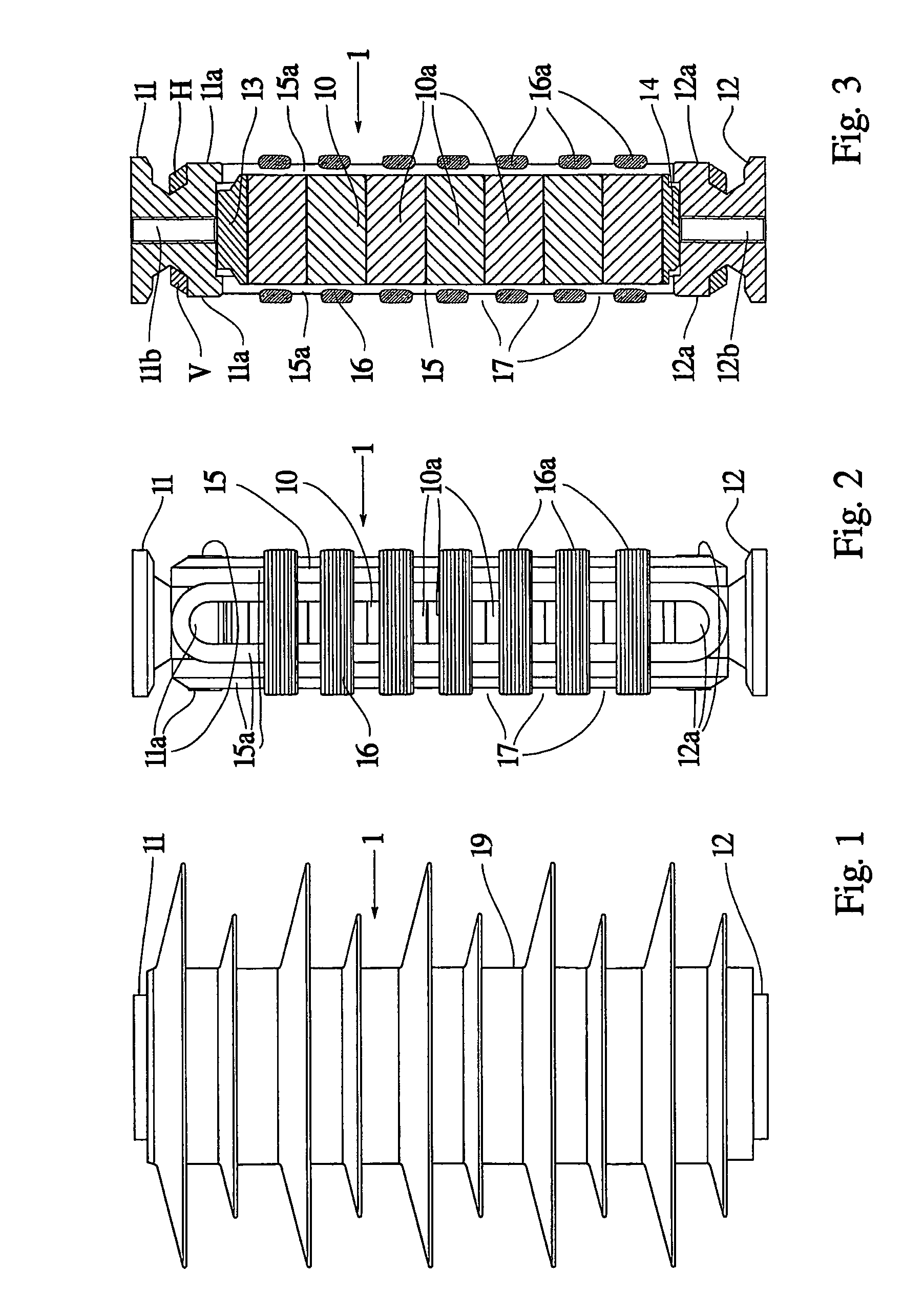
[0032]FIG. 1 shows a surge arrester 1 with an upper end electrode 11 and a lower end electrode 12 and an electrically insulating casing 19.

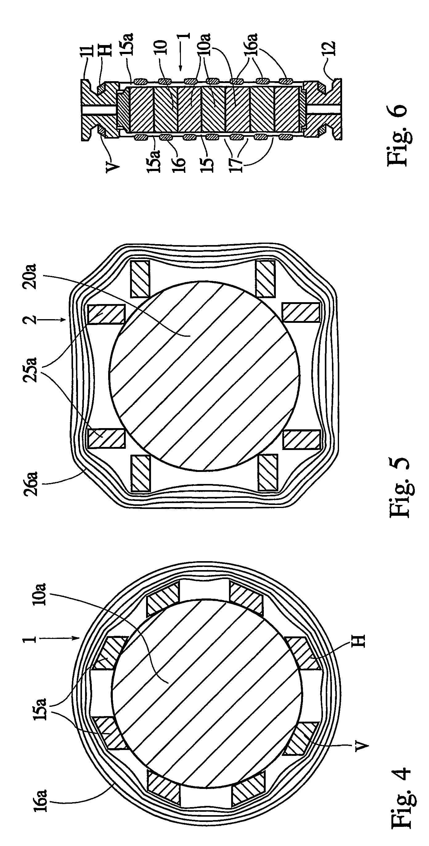
[0033]FIG. 2 shows a corresponding surge arrester 1 without the electrically insulating casing. A stack 10, comprising seven cylindrical varistor blocks 10a of circular cross section, is arranged between the upper end electrode 11 and the lower end electrode 12. The symmetry axes of the varistor blocks 10a coincide. The diameter of the varistor blocks 10a is 60 mm and their height 40 mm. Arranged around the stack 10 are clamping members 15 in the form of four loops, of which three 15a are shown in the figure. The loops 15a are wound of continuous glass fibre and impregnated with epoxy. The loops 15a run around the shoulders 11a of the upper end electrode 11 and the shoulders 12a of the lower end electrode 12 and clamp the end electrodes 11, 12 against the stack 10, thus creating the desired contact pressure between the varistor blocks 10a. The lo...


PUM


Abstract

A surge arrester including a stack of a plurality of cylindrical varistor blocks that are arranged one after the other in the axial direction of the varistor blocks between an upper end electrode and a lower end electrode. Arranged around the stack are clamping members of an insulating material including at least three loops of continuously wound fiber that connect the upper end electrode to the lower end electrode as well as a bursting-protective bandage in the form of a plurality of rings wound of fiber, and a surrounding, electrically insulating, outer casing of rubber or other polymeric material. The loops are wound from glass fiber and exhibit an asymmetrical cross section.

Description

TECHNICAL FIELD[0001]The present invention relates to a surge arrester comprising a stack of a plurality of cylindrical varistor blocks, which are arranged one after the other in the axial direction of the varistor blocks, between an upper end electrode and a lower end electrode. Arranged around the stack are clamping members of insulating material, comprising at least three loops of continuously wound fibre, which connect the upper end electrode to the lower end electrode, and a busting-protective bandage in the form of a plurality of rings or bands wound of fibre, and a surrounding, electrically insulating, outer casing of rubber or other polymeric material.BACKGROUND ART[0002]Surge arresters are used to protect expensive electrical equipment from overvoltages. A common product for this purpose are cylindrical blocks of metal oxide, for example zinc oxide, so-called varistors. These have the property that the resistance is high at low voltage but low at high voltage. When the oper...

Claims


Application Information

Patent Timeline
Patent Type & Authority Patents(United States)
IPC IPC(8): H02H1/00H02H7/04H02H9/06H01C7/12
CPCH01C7/12
Inventor SILJEHOLM, ROGEREKEROTH REIJM, KERSTIN
Owner HITACHI ENERGY LTD
Learn More