
Coherence of displayed images for split-frame rendering in multi-processor graphics system

a graphics system and multi-processor technology, applied in the field of graphics processing subsystems, can solve the problems of multi-chip graphics systems, frame coherence, and ensure the unity of all gpus

Active Publication Date: 2009-04-21
NVIDIA CORP
View PDF28 Cites 117 Cited by
  • Summary
  • Abstract
  • Description
  • Claims
  • Application Information

AI Technical Summary

Benefits of technology

[0024]According to a still further aspect of the present invention, a graphics processing system includes a number of graphics processors and a global control circuit. The graphics processors, which are configured to render different portions of a current image in parallel, each include a first frame buffer and a second frame buffer, a rendering module, and a communication module. The rendering module is configured to execute a stream of commands, including a first group of rendering commands instructing the graphics processor to write pixel data for a portion of the current image to the first frame buffer, and is further configured to assert a local ready signal when execution of the first group of rendering commands is complete. The communication module of each graphics processor is coupled to receive the local ready signal and is configured to propagate the local ready signal to the other graphics processors and to pause execution of the stream of rendering commands after the loca...

Problems solved by technology

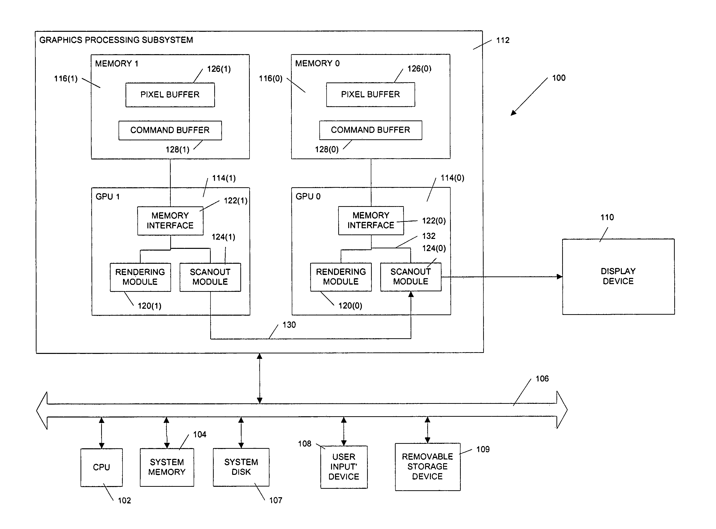
Multi-chip graphics systems present a variety of problems, among which is “frame coherence.” In a single-processor system, the GPU typically has a rendering module that generates image data and a scanout module that reads out pixels of the most recently rendered image to a display device.
In a multi-processor system implementing split-frame rendering, it is not guaranteed that all of the GPUs will finish rendering their portions of the new image at the same time.
If each GPU simply executes a buffer flip whenever it finishes its portion of the image, different portions of the displayed images will tend to become unsynchronized, leading to tearing and other visual artifacts.
However, it is difficult to maintain perfect balance where the image complexity is not static, as is usually the case for animated images.

Method used


Image

  • Coherence of displayed images for split-frame rendering in multi-processor graphics system
  • Coherence of displayed images for split-frame rendering in multi-processor graphics system
  • Coherence of displayed images for split-frame rendering in multi-processor graphics system

Examples


Embodiment Construction

[0038]Embodiments of the present invention provide systems and methods for coherent image display for a graphics processing systems having multiple processors operating in a split-frame rendering mode. As used herein “coherent image display” refers to updating portions of the displayed image that are rendered by different graphics processors in such a way that the portions form a consistent, coherent whole. For example, in a raster-based display device, all portions of the image would be updated during the same raster scan.

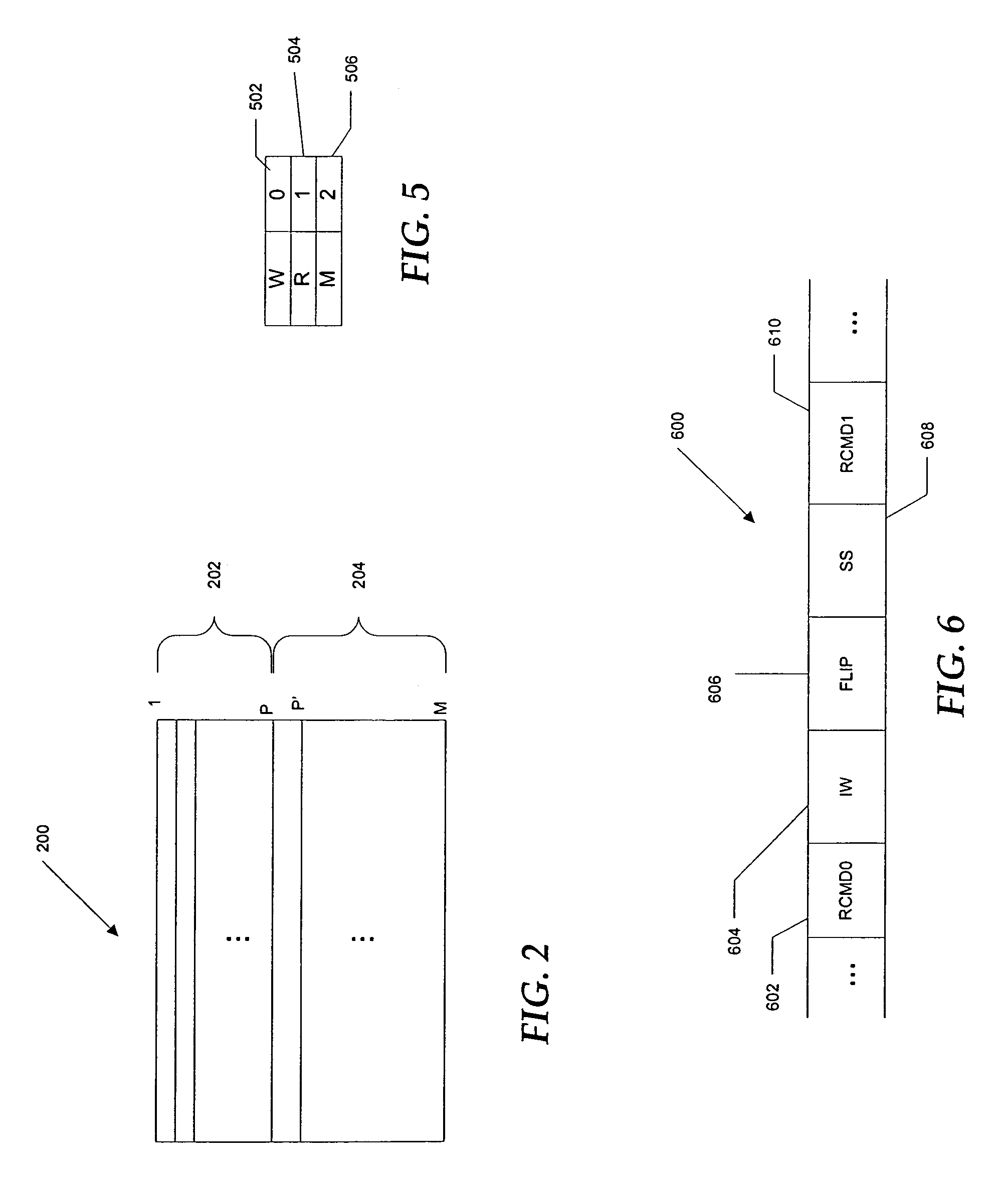
[0039]In split-frame rendering mode, the processors render different portions of a current image in parallel, writing pixel data to respective first frame buffers, while scanning out pixel data for a previous image from respective second frame buffers. As each processor completes rendering of its portion of the current image, it generates a local ready event (or signal), then pauses rendering operations. A synchronizing agent detects the local ready event and gene...


PUM


Abstract

Coherence of displayed images is provided for a graphics processing systems having multiple processors operating to render different portions of a current image in parallel. As each processor completes rendering of its portion of the current image, it generates a local ready event, then pauses its rendering operations. A synchronizing agent detects the local ready event and generates a global ready event after all of the graphics processors have generated local ready events. The global ready signal is transmitted to each graphics processor, which responds by resuming its rendering activity.

Description

CROSS-REFERENCES TO RELATED APPLICATIONS[0001]The present disclosure is related to the following commonly-assigned co-pending U.S. patent applications:[0002]application Ser. No. 10 / 639,893, filed Aug. 12, 2003, entitled “Programming Multiple Chips from a Command Buffer;”[0003]application Ser. No. 10 / 642,905, filed Aug. 18, 2003, entitled “Adaptive Load Balancing in a Multi-Processor Graphics Processing System;”[0004]application Ser. No. 10 / 726,351, filed Dec. 2, 2003, entitled “Interrupt Servicing for a Multiprocessor Subsystem”;[0005]application Ser. No. 10 / 789,248, filed Feb. 27, 2004, entitled “Graphics Device Clustering with PCI-Express;”[0006]application Ser. No. 10 / 990,712, filed Nov. 17, 2004, entitled “Connecting Graphics Adapters for Scalable Performance”; and[0007]application Ser. No. 11 / 012,394, filed Dec. 15, 2004, entitled “Broadcast Aperture Remapping for Multiple Graphics Adapters.”.[0008]The respective disclosures of these applications are incorporated herein by refe...

Claims


Application Information

Patent Timeline
IPC IPC(8): G06F15/16G09G5/36
CPCG06T15/005G09G5/397G09G5/12G09G5/399G09G2360/06
Inventor DIARD, FRANCK R.JOHNSON, PHILIP BROWNINGYOUNG, WAYNE DOUGLASLEDEBOHM, HERBERT O.
Owner NVIDIA CORP
Learn More