Vector controller for a permanent magnet synchronous motor, inverter module, and permanent magnet synchronous motor constant display system
a technology of synchronous motor and constant display system, which is applied in the direction of dynamo-electric converter control, motor/generator/converter stopper, dynamo-electric gear control, etc., can solve the problems of reducing control characteristics and reducing the precision of motor constant identification, and achieve high precision and torque control. high responsive
- Summary
- Abstract
- Description
- Claims
- Application Information
AI Technical Summary
Benefits of technology
Problems solved by technology
Method used
Image
Examples
first embodiment
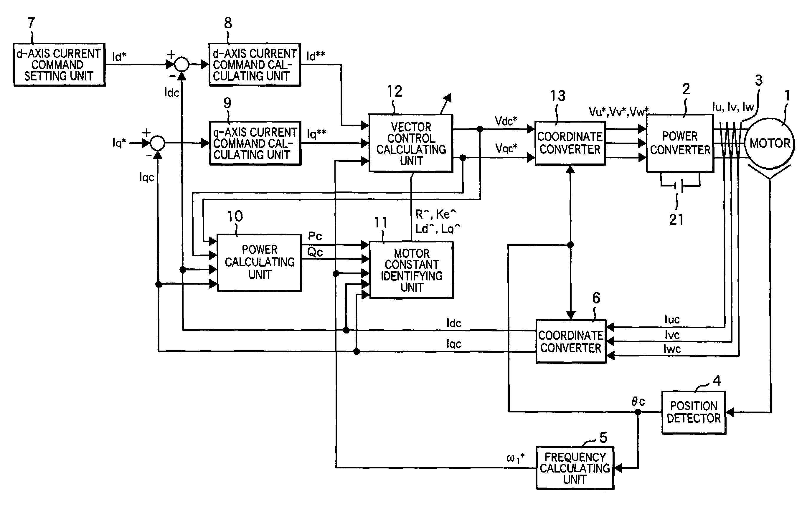
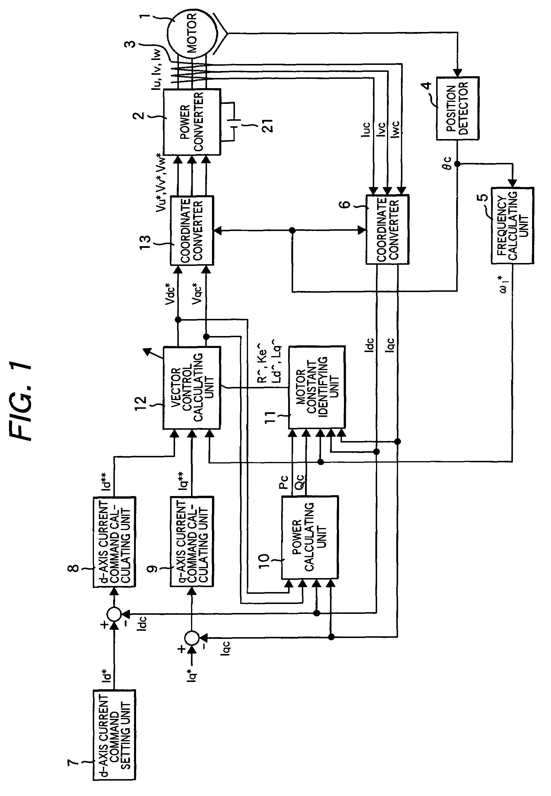
[0036]FIG. 1 shows an exemplary structure of a vector controller of a permanent magnet synchronous motor that embodies the present invention. The vector controller comprises a permanent magnet synchronous motor 1; a power converter 2 that outputs voltages in proportion to voltage command values Vu*, Vv*, and Vw* for three-phase AC currents; a DC power supply 21; a current detector 3 that detects three-phase AC currents Iu, Iv, and Iw; a position detector 4 that detects the position θ of the motor; a frequency calculating unit 5 that outputs a frequency ω1* calculated from a detected position θc; a coordinate converter 6 that outputs currents Idc and Iqc respectively detected on the d-axis and q-axis according to the detected three-phase AC currents Iuc, Ivc, and Iwc and the detected position θc; a d-axis current command setting unit 7 that sets a first d-axis current command value Id*; a d-axis current command calculating unit 8 that outputs a second d-axis current command value Id*...
second embodiment
[0126]In the method described in the first embodiment, the output values (R^, Ld^, Lq^, and Ke^) from the motor constant identifying unit 11 are used to set the motor constants of the vector control calculating unit 12. The output of the motor constant identifying unit 11 can also be used to modify control gains of second d-axis and q-axis current command calculating units 8a and 9a.
[0127]FIG. 11 shows the structure of a vector controller for a permanent magnet synchronous motor that implements a second embodiment of the present invention, which is implemented for the above-mentioned control gain modification. The reference numerals 1 to 7, 10 to 13, and 21 in FIG. 11 indicate the same elements having the same reference numerals in FIG. 1.
[0128]As indicated by equation (25), if identified motor constants (R^, Ld^, Lq^, and Ke^) are used to modify the control gains (Kp_d, Ki_d, Kp_q, and Ki_q) of the current command calculating units 8a and 9a, a highly precise, highly responsive to...
third embodiment
[0131]FIG. 12 shows the structure of a vector controller for a permanent magnet synchronous motor that implements yet another embodiment of the present invention. This embodiment uses a difference between a current command value given from a high-end unit and a detected current to compensate output values Vdc* and Vqc* in vector control calculation.
[0132]The reference numerals 1 to 7, 10, 11, 13 and 21 in FIG. 12 indicate the same elements having the same reference numerals in FIG. 1. A d-axis current control calculating unit 8b calculates a d-axis compensation voltage ΔVd so that the detected d-axis current Idc matches the d-axis current command value Id*. A q-axis current control calculating unit 9b calculates a q-axis compensation voltage ΔVq so that the detected q-axis current Iqc matches the q-axis current command value Iq*. A vector control calculating unit 12′ uses the d-axis and q-axis current command values Id* and Iq*, the calculated frequency ω1*, and the values (R^, Ld^,...
PUM
 Abstract
Description
Claims
Application Information
 - R&D
- Intellectual Property
- Life Sciences
- Materials
- Tech Scout
- Unparalleled Data Quality
- Higher Quality Content
- 60% Fewer Hallucinations
Browse by: Latest US Patents, China's latest patents, Technical Efficacy Thesaurus, Application Domain, Technology Topic, Popular Technical Reports.
© 2025 PatSnap. All rights reserved.Legal|Privacy policy|Modern Slavery Act Transparency Statement|Sitemap|About US| Contact US: help@patsnap.com


