
Energy saving outlet having a sensor and method of use thereof

a technology of energy saving outlet and sensor, which is applied in the direction of process and machine control, coupling device connection, instruments, etc., can solve the problems of accumulated power consumed and outlet without energy saving function, and achieve the effect of energy saving

Active Publication Date: 2009-04-21
POWERTECH INDAL
View PDF5 Cites 45 Cited by
  • Summary
  • Abstract
  • Description
  • Claims
  • Application Information

AI Technical Summary

Benefits of technology

"The present invention provides an energy saving outlet that can turn off its power when the electrical equipment is in a stand-by state to save energy. The outlet has a sensor, control unit, and relay to determine if the starting signal is an error signal or not. The control unit will turn off the relay after a certain time if the current amount remains unchanged, and will turn off the power to the outlet if the current amount approaches a reference value and remains for a second certain time. This outlet can eliminate the stand-by current and save power during the stand-by state. The energy saving method by using the outlet involves recording the current amount of the outlet, determining if the current amount is changed, and turning off the relay to save power during the stand-by state."

Problems solved by technology

Although the stand-by current is not huge even minor, but the electrical equipment must be turned ON long-term, therefore, the accumulated power consumed is very significant.
Furthermore, the electrical equipment is generally plugged into an outlet for getting the power supply, however, the outlet maybe has a surge absorbing or overload protecting function, but the prior art outlet does not have the energy saving function.

Method used


Image

  • Energy saving outlet having a sensor and method of use thereof
  • Energy saving outlet having a sensor and method of use thereof
  • Energy saving outlet having a sensor and method of use thereof

Examples


Embodiment Construction

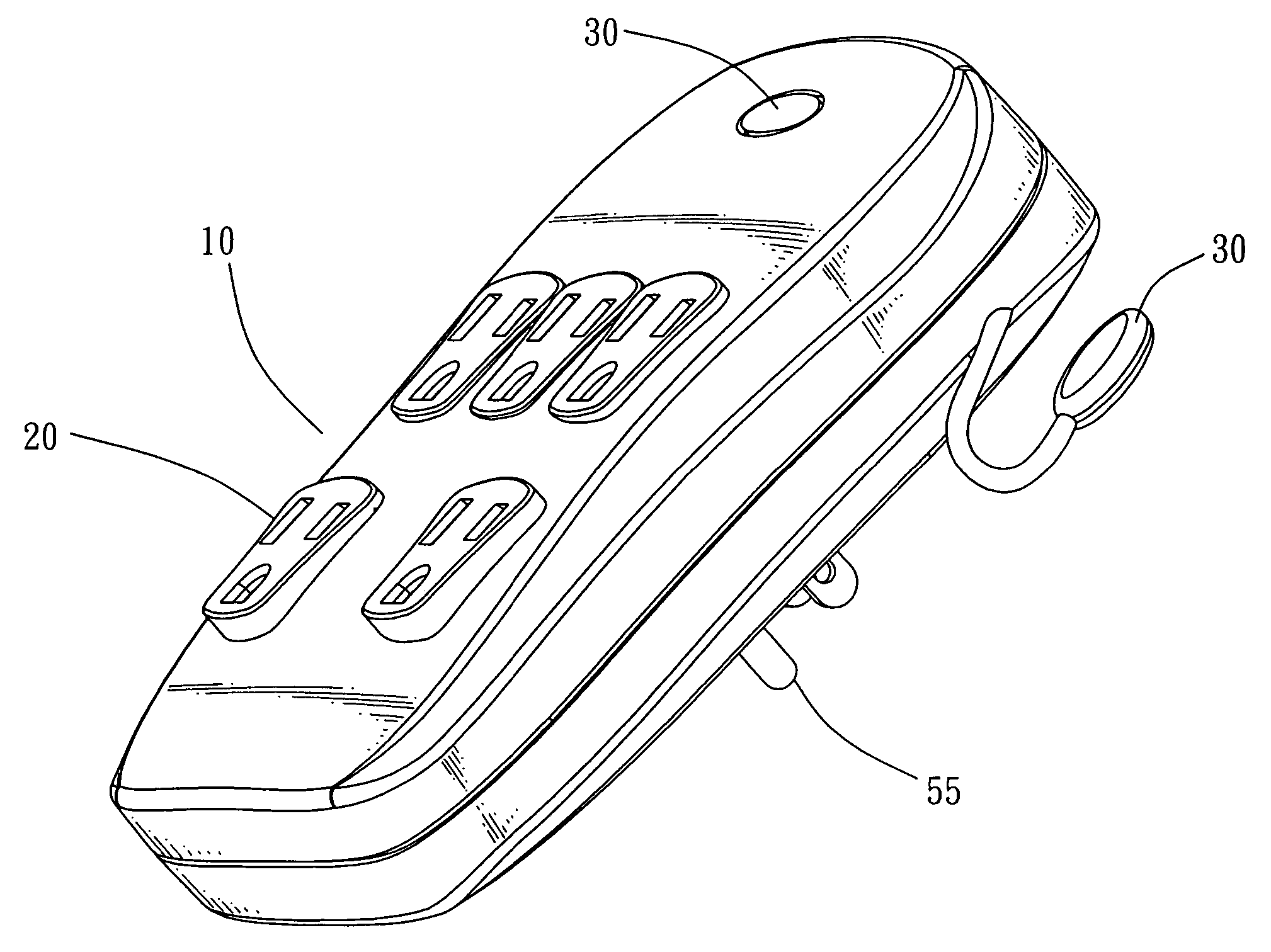
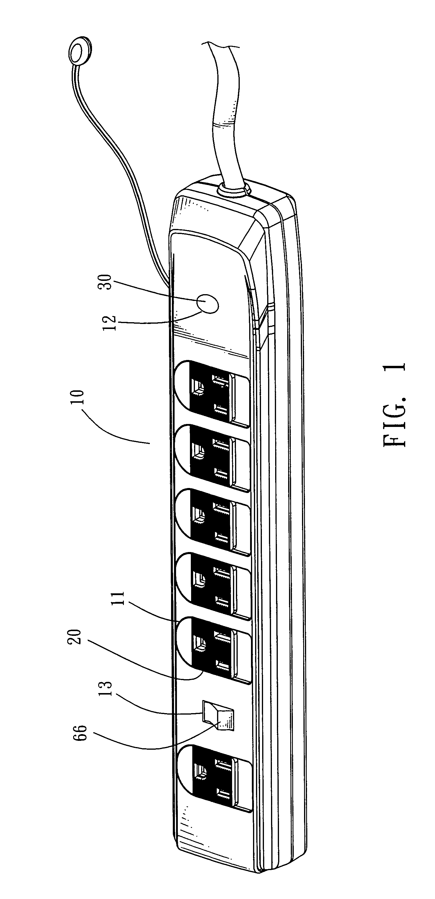
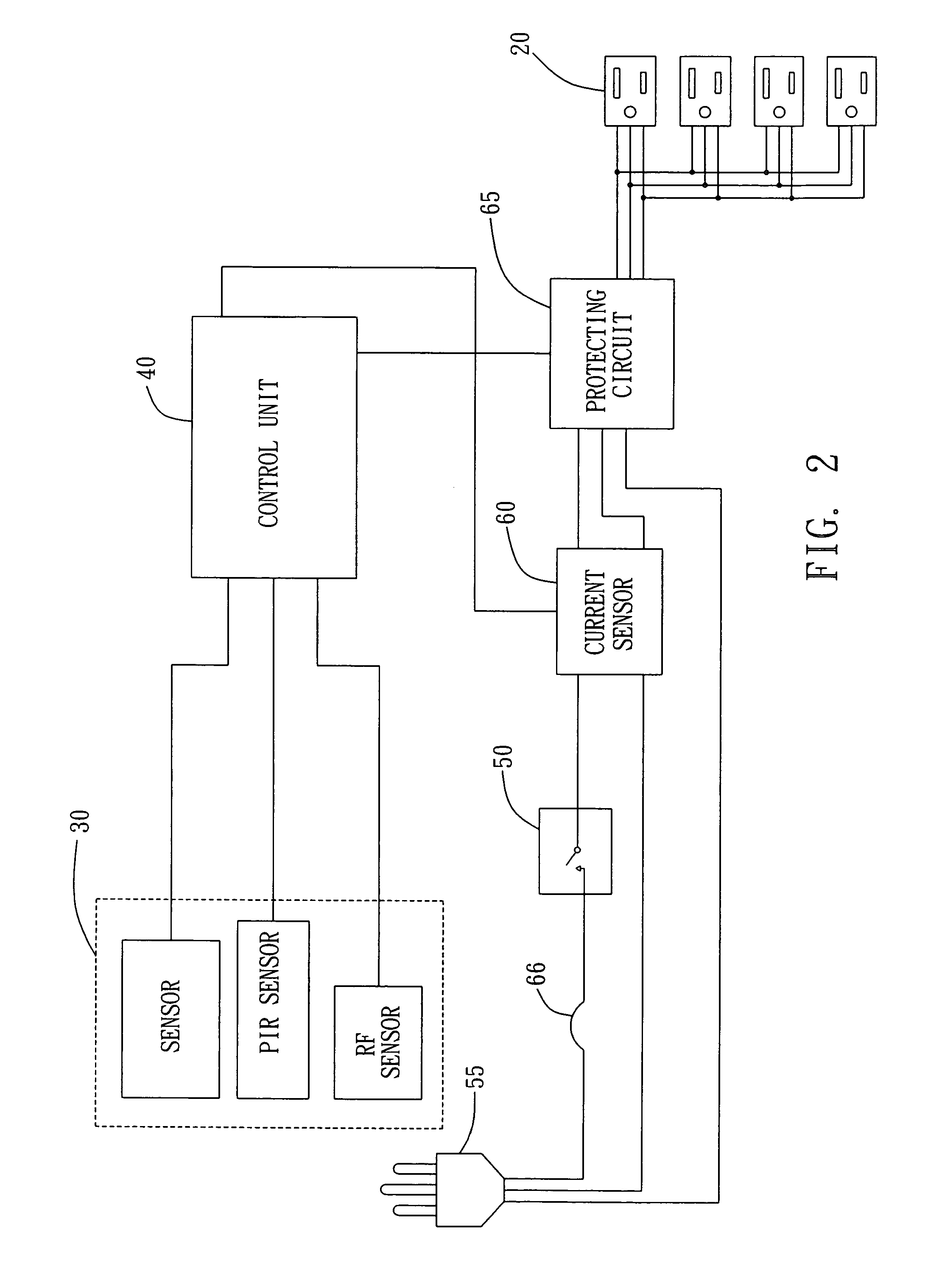
[0020]Referring to FIGS. 1˜2, wherein the FIG. 1 shows an assembly view of an energy saving outlet according to one embodiment of the present invention; while the FIG. 2 shows a block diagram of the energy saving outlet according to one embodiment of the present invention. As shown in the Figs. the energy saving outlet of the present invention mainly comprises: a housing 10; at least one outlet 20; a sensor 30; a control unit 40 and a relay 50.

[0021]Wherein, the housing 10 is made of the insulation material, for example but not limited to a plastic material and has at least one first opening 11 and a second opening 12 thereon, for disposing the outlet 20, sensor 30; control unit 40 and relay 50.

[0022]The outlet 20 is a general AC 110V or 220V 2 holes or 3 holes power outlet and disposed in the housing 10 as well as exposed the first opening 11 for providing a plug of an electrical equipment (not shown) being plugged into and get the required operating power. Wherein, the amount (i.e...


PUM


Abstract

The present invention relates to an energy saving outlet, which comprises: a housing, having at least one first opening and a second opening thereon, for disposing the following elements at least one outlet, disposed in the housing and exposed the first opening, for providing an electrical equipment being plugged into; a sensor, disposed in the housing and exposed the second opening, for sensing a starting signal of the electrical equipment; a control unit, disposed in the housing and coupled to the sensor, for outputting a control signal when it receives the starting signal; a relay, one end being coupled to a power input terminal, and another end being coupled to the control unit, for being changed to an on or off state through the control signal; thereby the energy saving outlet can turn OFF its power when the electrical equipment has entered a stand-by state, so as to achieve the goal of energy saving. Furthermore, the present invention also provides an energy saving method by using an outlet.

Description

REARGROUND OF THE INVENTION[0001]1. Field of the Invention[0002]The present invention relates to an energy saving outlet, more particularly, it relates to an energy saving outlet which can turn OFF its power when the electrical equipment is in a stand-by state, and to turn ON its power when it senses a starting signal of the electrical equipment so as to achieve the goal of energy saving.[0003]2. Description of the Related Art[0004]In general, the electrical equipment, such as television, DVD player or air conditioner, generally has a remote control function, so that the user can easily control the electrical equipment by using a remote controller. The remote controllable electrical equipment must be turned ON its power and entered a stand-by state so as to enable the electrical equipment to receive the control signal(s) from the remote controller, thus the electrical equipment will cause stand-by current and consume power. Although the stand-by current is not huge even minor, but t...

Claims


Application Information

Patent Timeline
Patent Type & Authority Patents(United States)
IPC IPC(8): H01R25/00
CPCH01R25/003H01R13/7038
Inventor CHOU, JONIELEE, YU-LUNG
Owner POWERTECH INDAL
Learn More