
Structure for improving performance of an active headrest

a technology of active headrest and performance, which is applied in the direction of pedestrian/occupant safety arrangement, vehicle components, vehicle arrangement, etc., can solve the problems of insufficient functioning of active headrest, inability to operate in time, etc., and achieve the effect of reducing the operating time of active headrest and quickly supporting the head and the neck of an occupan

Active Publication Date: 2009-04-21
KIA MOTORS CORP
View PDF14 Cites 1 Cited by
  • Summary
  • Abstract
  • Description
  • Claims
  • Application Information

AI Technical Summary

Benefits of technology

[0009]The present invention provides an active headrest which reduces the operating time thereof so as to quickly support the head and the neck of an occupant.
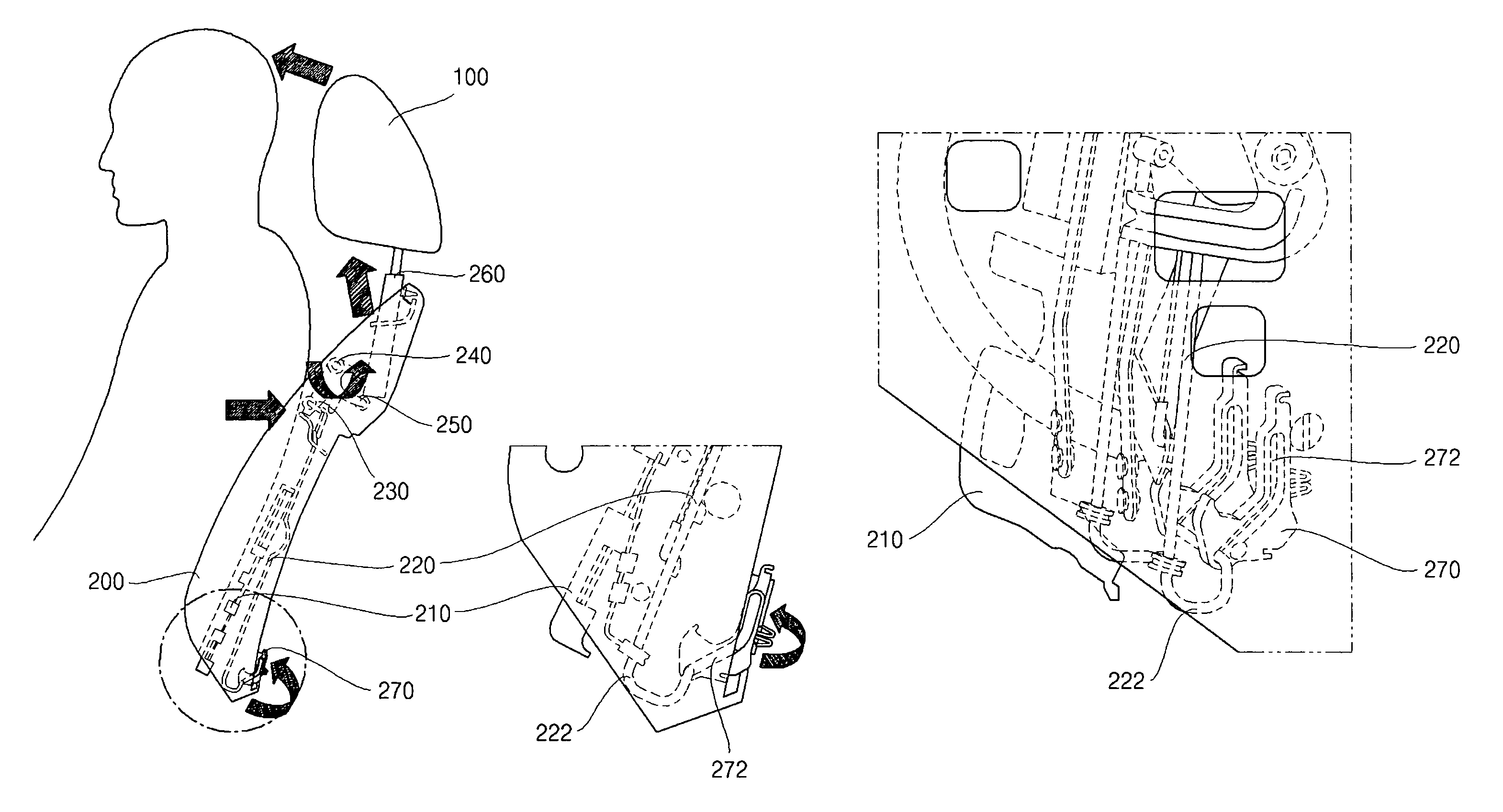
[0011]In one embodiment, a structure for improving performance of an active headrest comprises a lumbar support plate which is installed within a seat back frame and supports the body of an occupant; a lumbar support interlocking wire which operates by being interlocked with the lumbar support plate and a link bracket which is disposed on the lumbar support interlocking wire and is rotated by the lumbar support interlocking wire so as to rotate a link connecting pipe which raises an active headrest pipe; a stopper which is disposed behind the active headrest pipe and is installed to an inner side of the seat back frame; and a hooking projection which supports a lower end portion of the active headrest pipe such that the active headrest pipe cannot go down at an operated position of the active headrest being formed in the stopper.

Problems solved by technology

However, there have been issues with the operating time of the active headrest not acting in time support the head and the neck of an occupant when a vehicle is impacted.
Furthermore, there have also been issues with active headrest not functioning properly after a vehicle has been impacted.

Method used


Image

  • Structure for improving performance of an active headrest
  • Structure for improving performance of an active headrest
  • Structure for improving performance of an active headrest

Examples


Embodiment Construction

[0023]An exemplary embodiment of the present invention will hereinafter be described in detail with reference to the accompanying drawings.

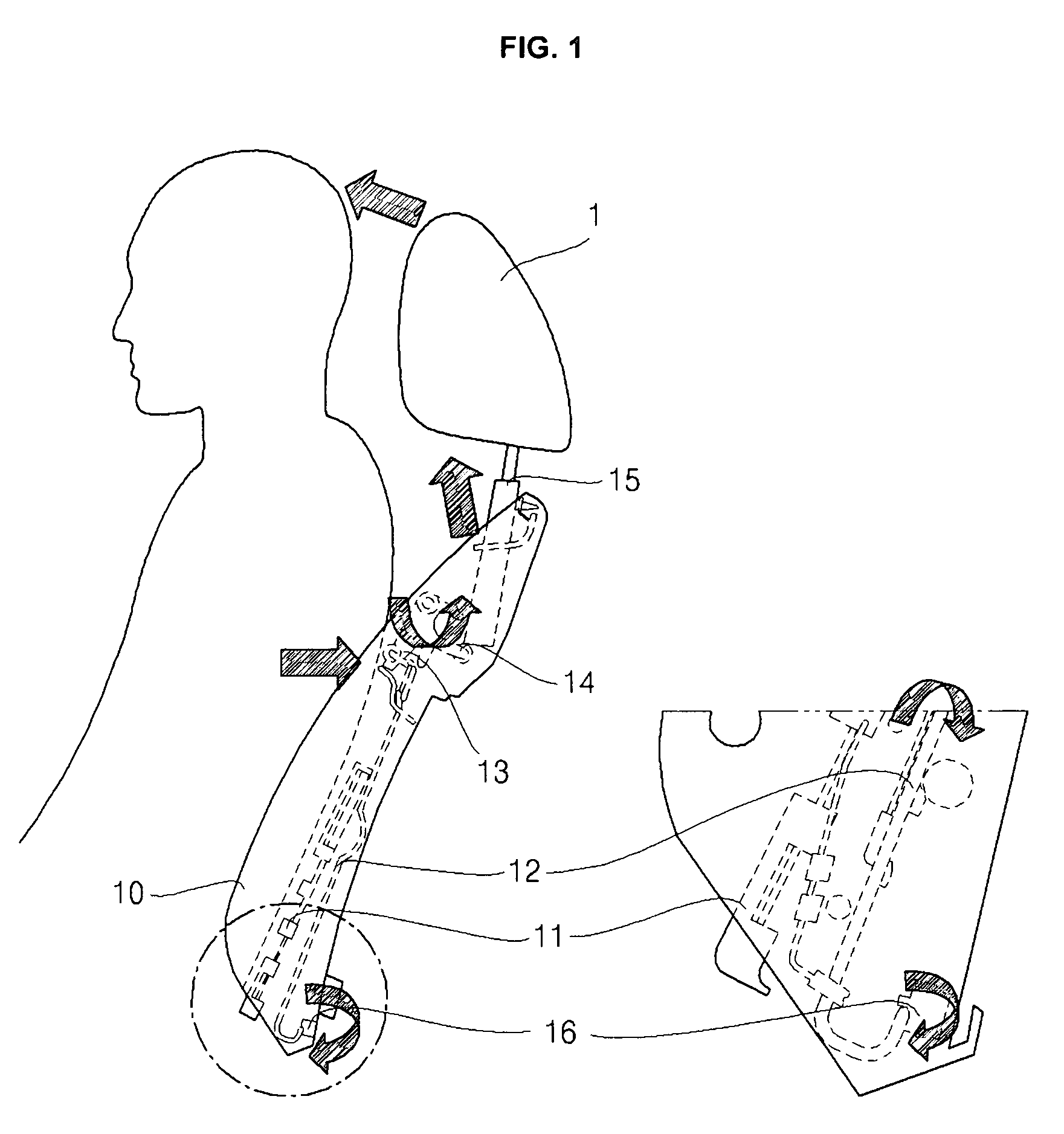
[0024]As shown in FIG. 1 and FIG. 2, a conventional active headrest 1 is driven by a lumbar support plate 11 which is disposed inside a seat back frame 10 and supports the body of an occupant. One end of a lumbar support interlocking wire 12 is interlocked with the lumbar support plate 11 and the second end, which is coupled to a link connecting pipe 14 and a link bracket 13, is rotated by the lumbar support interlocking wire 12 so as to rotate the link connecting pipe 14 and raise an active headrest pipe 15.

[0025]When a vehicle is impacted, the body of an occupant compresses the lumbar support plate 11, the lumbar support plate 11 pushes the lumbar support interlocking wire 12, thereby rotating the link bracket 13.

[0026]While the link bracket 13 rotates, the link bracket 13 raises the link connecting pipe 14, thereby allowing the active headrest...


PUM


Abstract

A structure for improving performance of an active headrest comprises a lumbar support plate which is installed within a seat back frame and supports the body of an occupant; a lumbar support interlocking wire which operates by being interlocked with the lumbar support plate and a link bracket which is disposed on the lumbar support interlocking wire and is rotated by the lumbar support interlocking wire so as to rotate a link connecting pipe which raises an active headrest pipe; a stopper which is disposed behind the active headrest pipe and is installed to an inner side of the seat back frame; and a hooking projection which supports a lower end portion of the active headrest pipe such that the active headrest pipe cannot go down during a vehicle impact.

Description

CROSS-REFERENCE TO RELATED APPLICATION[0001]This application claims priority to Korean Patent Application No. 10-2006-0075711 filed in the Korean Intellectual Property Office on Aug. 10, 2006, the disclosure of which is incorporated herein by reference.BACKGROUND OF THE INVENTION[0002](a) Field of the Invention[0003]The present invention relates to a structure for improving performance of an active headrest.[0004](b) Description of the Related Art[0005]An active headrest is a general term for a headrest which automatically rises when a vehicle is impacted. The active headrest supports the head of an occupant, thereby protecting the head and the neck of an occupant.[0006]The active headrest operates by being interlocked with a seat thereby preventing an occupant from suffering major injuries. The active headrest moves upward and forward so as to support the head and the neck of an occupant.[0007]However, there have been issues with the operating time of the active headrest not acting...

Claims


Application Information

Patent Timeline
IPC IPC(8): B60N2/427B60R21/00
CPCB60N2/4885B60N2/888B60N2/42
Inventor KIM, SANG HO
Owner KIA MOTORS CORP
Learn More