
Multi-substrate integrated sensor

a sensor and multi-substrate technology, applied in the field of electric sensors, can solve the problems of low bandwidth, large height and circuit board area of typical current sensors, and low bandwidth

Inactive Publication Date: 2009-04-14
ALLEGRO MICROSYSTEMS INC
View PDF80 Cites 118 Cited by
  • Summary
  • Abstract
  • Description
  • Claims
  • Application Information

AI Technical Summary

Benefits of technology

The integrated circuit provides improved accuracy, reduced size, and increased bandwidth by maintaining a zero magnetic field, thereby minimizing linearity and sensitivity errors and reducing susceptibility to external magnetic fields.

Problems solved by technology

However, in conventional open and closed loop current sensors, the secondary conductor and / or the primary conductor are not integrated with the magnetic field transducer.
In part because this conventional closed loop current sensor is relatively large, it suffers from relatively low bandwidth.
As with the previously described conventional closed loop current sensor, in part because this conventional closed loop current sensor is relatively large, it suffers from relatively low bandwidth.
Typical current sensors tend to be undesirably large, both in terms of height and circuit board area, due in part to the secondary conductor and / or primary conductor being separate from the magnetic field transducer.
Such devices also tend to suffer inaccuracies due, in part, to variation of relative position of the primary conductor, the magnetic field transducer, and the secondary conductor.
While conventional current sensors are described above as having particular disadvantages, it will be appreciated that conventional external magnetic field sensors and also conventional electrical signal isolators suffer from the same disadvantages.

Method used


Image

  • Multi-substrate integrated sensor
  • Multi-substrate integrated sensor
  • Multi-substrate integrated sensor

Examples


Embodiment Construction

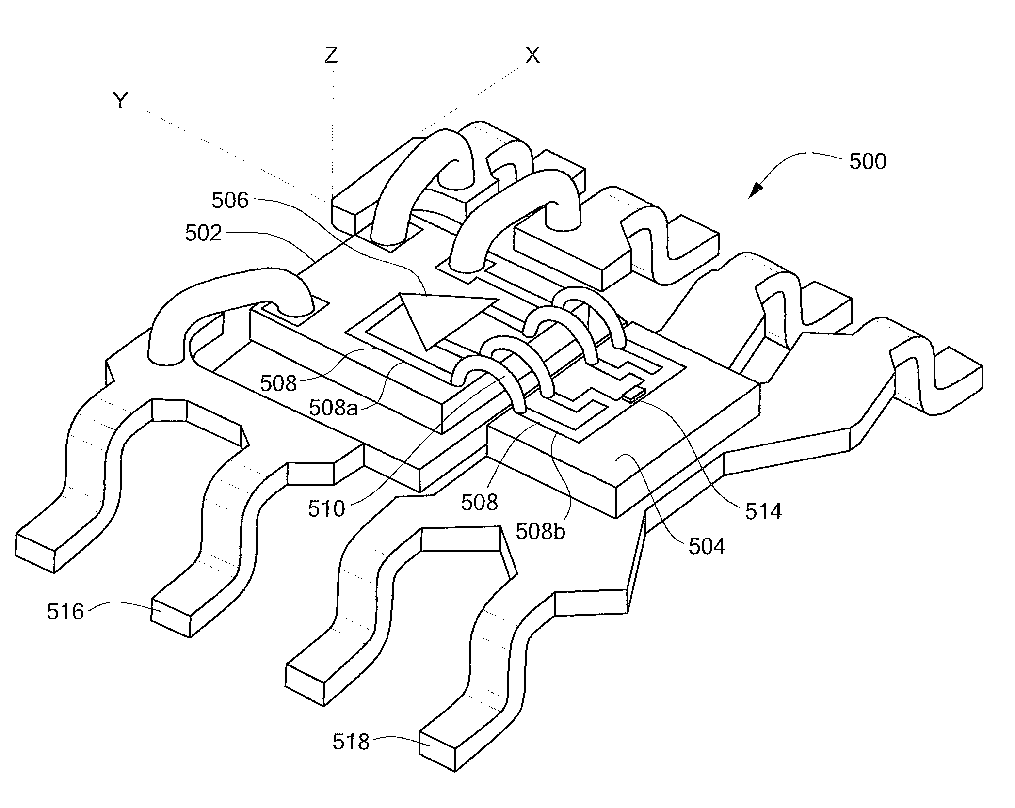
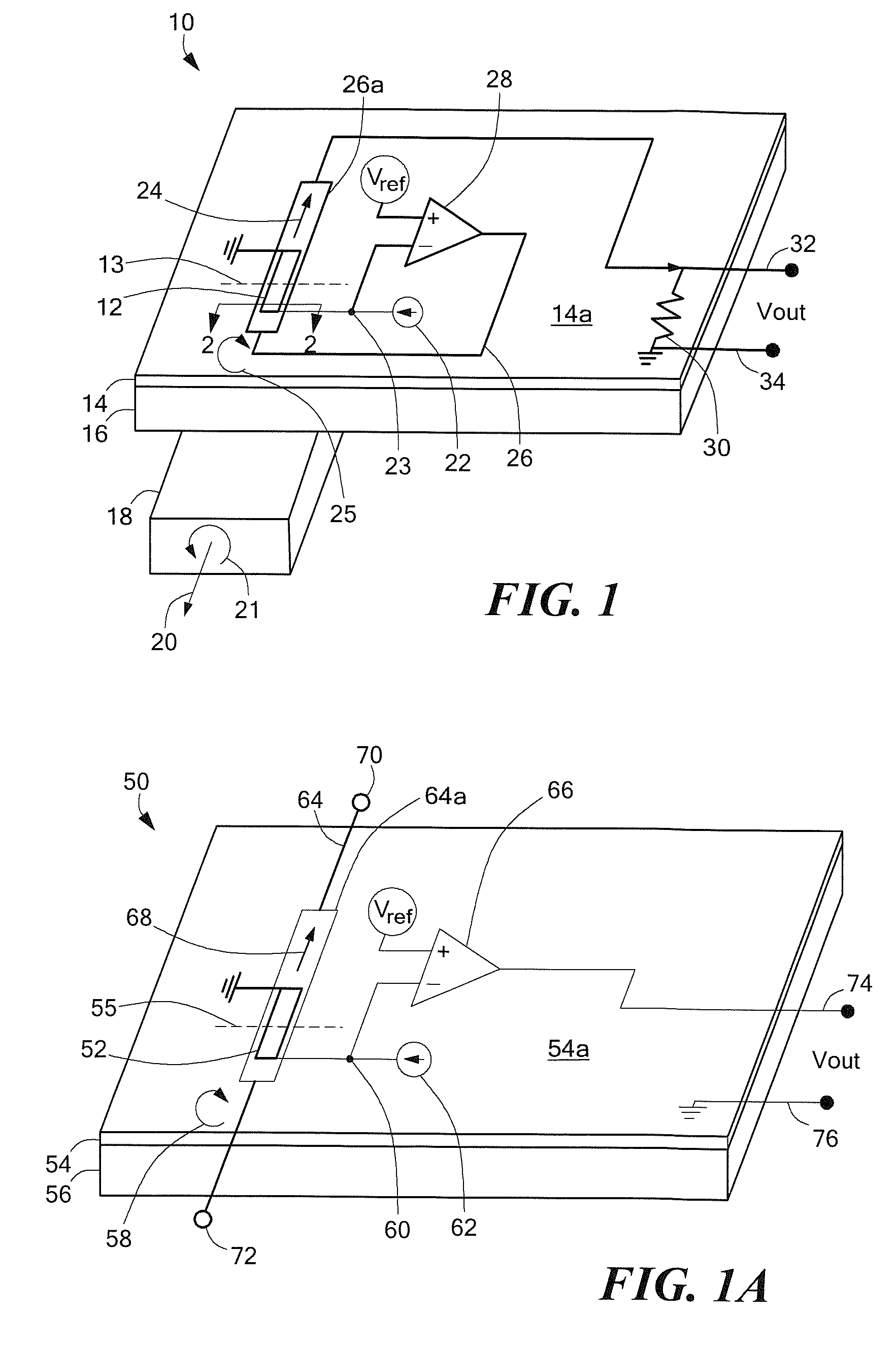
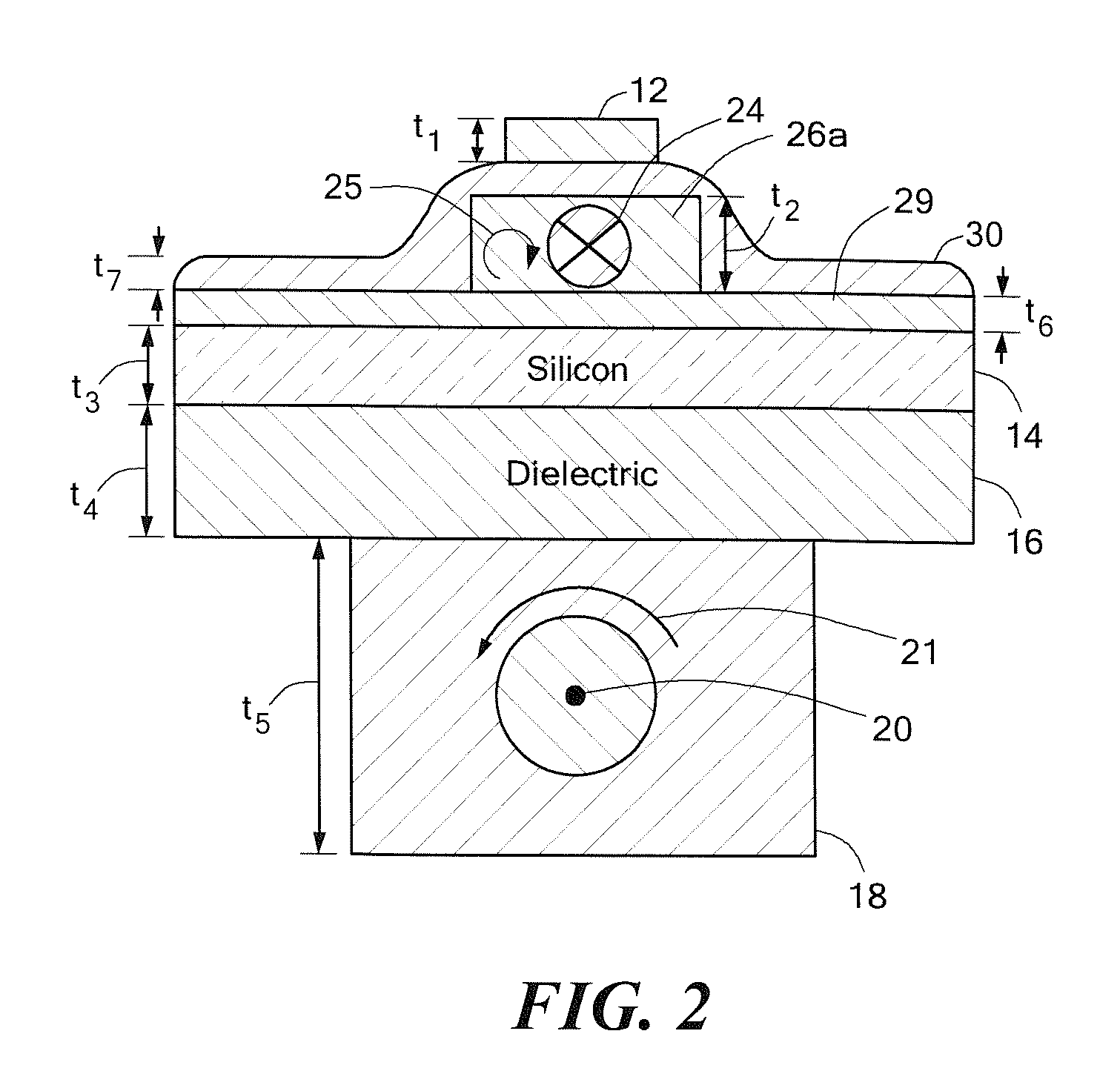
[0030]Referring to FIG. 1, an electronic circuit 10 includes a silicon substrate 14, a magnetic field transducer 12 disposed over a surface 14a of the silicon substrate, and a conductor 26 disposed over the surface 14a of the silicon substrate proximate to the magnetic field transducer 12. With this arrangement, an integrated circuit is provided which is suitable for various applications, such as a current sensor (FIGS. 1, 1A, 3 and 4), a magnetic field sensor (FIGS. 6 and 6A), and a signal isolator (FIGS. 7 and 7A).

[0031]The electronic circuit 10 can be used in open loop configurations in which a current passes through the conductor 26 (see FIG. 1A) or in closed loop configurations in which a further conductor 18 is also used. The conductor 18 is isolated from the silicon substrate 14 by a dielectric 16, as shown. In closed loop applications, in which both the conductor 18 and conductor 26 are used, the conductor 18 is referred to as the primary conductor and conductor 26 is referr...


PUM


Abstract

An electronic circuit includes a first substrate having a first substrate surface and a device supported by the first substrate surface. The device is selected from among a passive electronic component and an active electronic component. The electronic circuit also includes a second substrate having a second substrate surface and a conductor proximate to the second substrate. The electronic circuit also includes a magnetic field transducer disposed over the conductor and coupled to the device and an insulating layer disposed between the conductor and the second substrate. The conductor is adapted to carry an electrical current to generate a first magnetic field. The electronic circuit is responsive to the first magnetic field. In some embodiments, the conductor is a secondary conductor and the circuit further includes a primary conductor disposed proximate to the magnetic field transducer and an insulating layer disposed between the primary conductor and the second substrate.

Description

CROSS-REFERENCE TO RELATED APPLICATIONS[0001]This application is a Divisional Application of and claims the benefit of U.S. patent application Ser. No. 10 / 364,442 filed Feb. 11, 2003, now U.S. Pat. No. 7,259,545, which is incorporated herein by reference in its entirety.STATEMENT REGARDING FEDERALLY SPONSORED RESEARCH[0002]Not Applicable.FIELD OF THE INVENTION[0003]This invention relates generally to electrical sensors and, more particularly, to a miniaturized integrated sensor having a magnetic field transducer and a conductor disposed on a substrate. The integrated sensor can be used to provide a current sensor, an isolator, or a magnetic field sensor.BACKGROUND OF THE INVENTION[0004]As is known in the art, conventional current sensors can be arranged in either an open loop or a closed loop configuration. An “open loop” current sensor includes a magnetic field transducer in proximity to a current-carrying, or primary, conductor. The magnetic field transducer provides an output sig...

Claims


Application Information

Patent Timeline
Patent Type & Authority Patents(United States)
IPC IPC(8): G01R15/20G01R33/09H10N50/10
CPCG01R15/205G01R33/09H01L2224/48091H01L2224/48137H01L2224/48247H01L2224/4903G01R15/207H01L2924/00014
Inventor STAUTH, JASONDICKINSON, RICHARDFORREST, GLENNVIG, RAVI
Owner ALLEGRO MICROSYSTEMS INC
Learn More