
Ink cartridge

a technology of ink cartridges and ink cartridges, applied in the field of ink cartridges, can solve the problems of deteriorating image quality, disturbing the normal printing operation, and limited ink feeding capability of ink cartridges, so as to improve the injection molding ability of ink cartridges, improve the configuration, and reduce manufacturing costs

Inactive Publication Date: 2009-04-14
S PRINTING SOLUTION CO LTD
View PDF14 Cites 2 Cited by
  • Summary
  • Abstract
  • Description
  • Claims
  • Application Information

AI Technical Summary

Benefits of technology

[0011]The present invention has been developed in order to solve the above drawbacks and other problems associated with the conventional arrangement. An aspect of the present invention is to provide an ink cartridge with an improved configuration that improves the injection-moldability of the ink cartridge, thereby lowering the manufacturing costs and preventing leakage of ink and mixture of colors.

Problems solved by technology

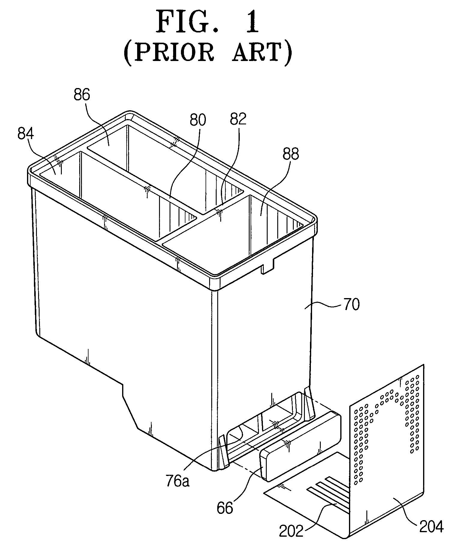
However, the ink cartridge as described above has a limited ink feeding capability because it is difficult to form cavities for feeding ink to the TAB circuit 204.
Consequently, droplets of ink fed to a print head (not shown) via the cavities 202 become irregular, thereby deteriorating the quality of image.
In such a case, the electrical connection to the ink cartridge 50 may be out of order, thereby disturbing the normal printing operation and reducing the reliability of the product.
As a result, there is problem in that the shape of the plug 66 becomes complicated, whereby manufacturing costs can be increased and leakage of inks and mixture of colors can be produced in the sealed portion.
Such a large volume may counterbalance negative pressure caused by capillary attraction produced by a foam member for containing ink, thereby deteriorating the characteristic of negative pressure.
However, this may result in additional processes when fabricating a mold and increase the material costs.

Method used


Image

  • Ink cartridge
  • Ink cartridge
  • Ink cartridge

Examples


Embodiment Construction

[0027]Certain embodiments of the present invention will now be described in greater detail with reference to the accompanying drawings.

[0028]In the following description, the same drawing reference numerals are used for the same features and structures throughout the drawings. The matters defined in the description such as a detailed construction and elements are provided to assist in a comprehensive understanding of the invention. Thus, it is apparent that the present invention can be carried out with variations in the described embodiments. Also, well-known functions or constructions are omitted for conciseness.

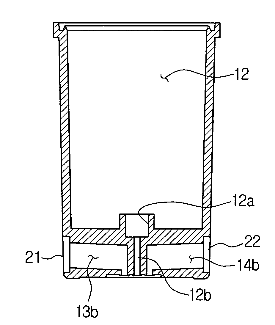
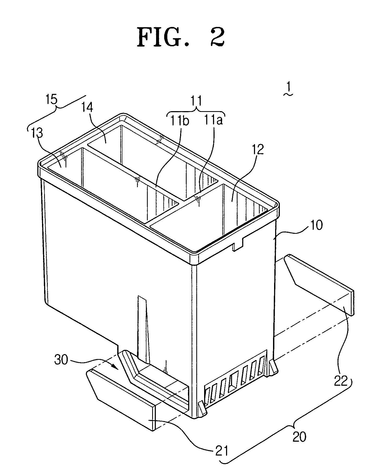
[0029]As shown in FIG. 2, the ink cartridge 1 comprises an ink cartridge body 10 with front and rear ink chambers 12, 15 formed in the interior of the ink cartridge body 10. the front and rear ink chambers 12 and 15 are defined by partitioning walls 11a and 11b that orthogonally intersect with one another. Additionally, the rear ink chamber 15 is divided into left and right...


PUM


Abstract

Disclosed is an ink cartridge for an ink-jet image forming apparatus. The ink cartridge comprises an ink cartridge body having a plurality of ink chambers. The ink chambers are formed by two or more partitioning walls orthogonally intersected with each other within the ink cartridge body. A nose is formed at a position adjacent to the bottom surfaces of the ink chambers. The nose includes openings formed in the opposite sides and a plurality of ink feeding channels forming the central area between the openings and connected to the ink feeding channels, respectively. Sealing members seal each corresponding one of the nose openings.

Description

CROSS-REFERENCE TO RELATED APPLICATIONS[0001]This application claims the benefit under 35 U.S.C. §119(a) of Korean Patent Application No. 2004-07970 filed Feb. 6, 2004, in the Korean Intellectual Property Office, the disclosure of which is incorporated herein by reference in its entirety.BACKGROUND OF THE INVENTION[0002]1. Field of the Invention[0003]The present invention relates to an ink cartridge. In particular, the present invention relates to a color ink cartridge preferably using three colors, such as cyan, magenta and yellow, and having discrete ink feeding passages for the ink of respective colors.[0004]2. Description of the Related Art[0005]In general, an ink-jet printer prints out a desired image by spraying ink onto printing paper. The ink-jet printer is provided with an ink cartridge as a consumable article for storing a predetermined quantity of ink. Representative prior art examples of ink-jet printers have been disclosed in U.S. Pat. Nos. 5,926,195, 6,260,961 and 6,29...

Claims


Application Information

Patent Timeline
Patent Type & Authority Patents(United States)
IPC IPC(8): B41J2/175B41J2/05
CPCB41J2/17513B41J2/17503B41J2/14032B41J2002/14306B41J2002/14193
Inventor JUNG, MYUNG-SONGLEE, YOUNG-SOO
Owner S PRINTING SOLUTION CO LTD
Learn More