
Image forming apparatus and liquid removal capability setting method

a technology of image forming apparatus and liquid removal capability, which is applied in the direction of typewriters, printing, other printing apparatus, etc., can solve the problems of image degradation, rear-side image transfer, cockling, and insufficient handling of recording media of different types, so as to prevent image defects, reduce the adhesion of ink coloring material, and prevent image degradation.

Inactive Publication Date: 2009-04-14
FUJIFILM CORP
View PDF4 Cites 10 Cited by
  • Summary
  • Abstract
  • Description
  • Claims
  • Application Information

AI Technical Summary

Benefits of technology

This approach enables efficient liquid removal while preventing image defects and ensuring the image quality by optimizing the liquid removal capability according to the type and surface characteristics of the recording medium, thereby maintaining the integrity of the image on the medium.

Problems solved by technology

Liquid (ink solvent) remains on the surface of the recording medium on which the image is formed, and this can be the cause of image degradation (image defects), rear-side image transfer, cockling, and the like.
However, in the related art, the liquid is removed by placing an absorbing body in contact with the recording medium and pressing the absorbing body against the recording medium, and this is insufficient for handling recording media of different types, thicknesses, surface characteristics, and the like.
For example, since an absorbing body is pressed against the recording medium at a prescribed pressure when removing the liquid on the recording medium, regardless of the type, thickness or surface properties of the recording medium, and the like, then in a recording medium having low surface smoothness, the ink coloring material is more liable to adhere to the absorbing body, compared to a recording-medium having high smoothness, and hence there is a risk of image defects, reduced density, and a concern that coloring material which once becomes attached to the absorbing body adheres to another sheet of recording medium.
In the ink absorbing body and image forming apparatus and method using the ink absorbing body described in Japanese Patent Application Publication No. 2001-179959, and the transfer type inkjet printer described in Japanese Patent Application Publication No. 2003-136689, there is no disclosure regarding the absorption force of the ink absorbing body, or restriction of this force, and hence there is a risk of ink coloring material becoming attached to the ink absorbing body.

Method used


Image

  • Image forming apparatus and liquid removal capability setting method
  • Image forming apparatus and liquid removal capability setting method
  • Image forming apparatus and liquid removal capability setting method

Examples


first embodiment

General Composition of Inkjet Recording Apparatus

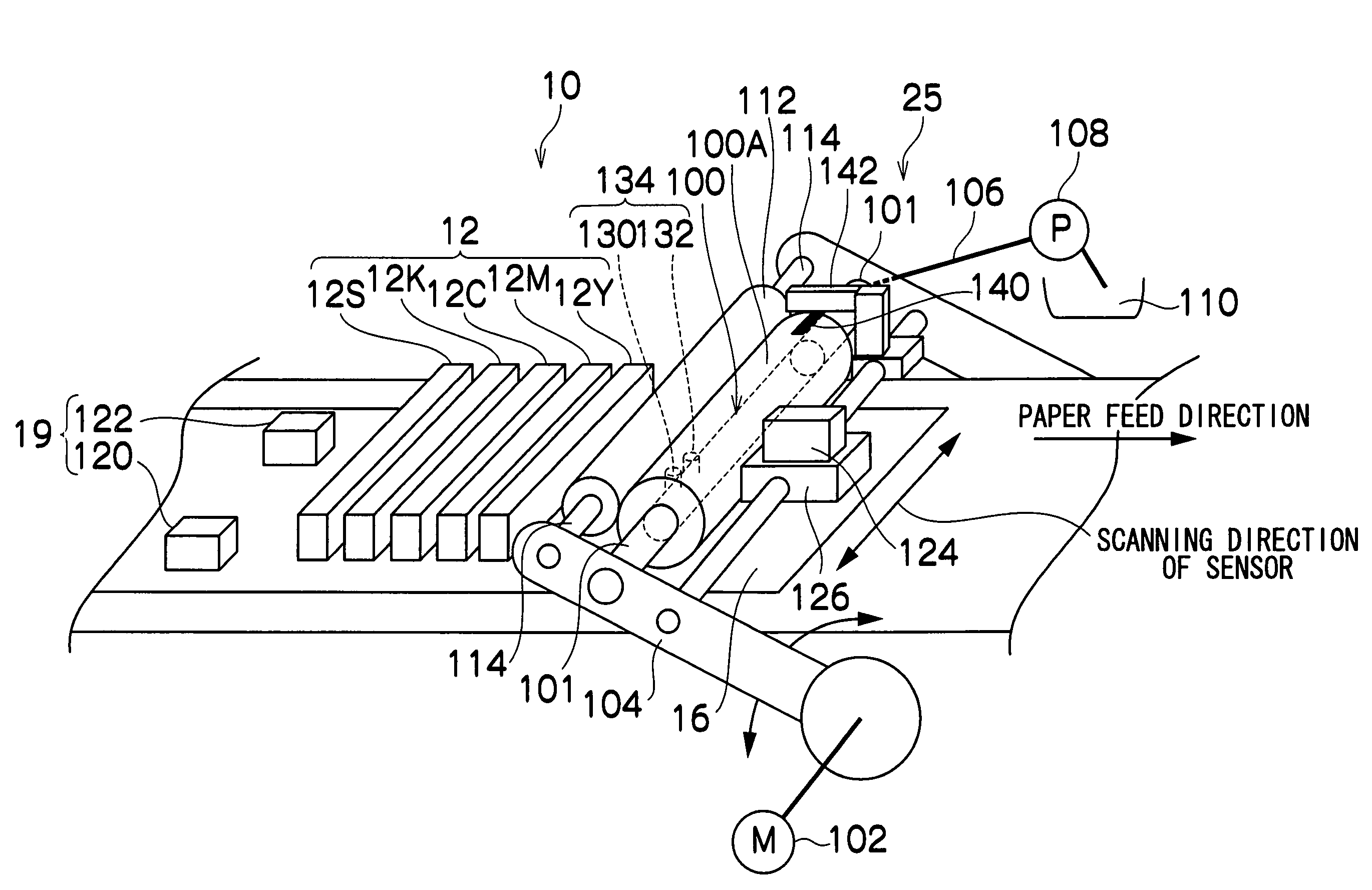
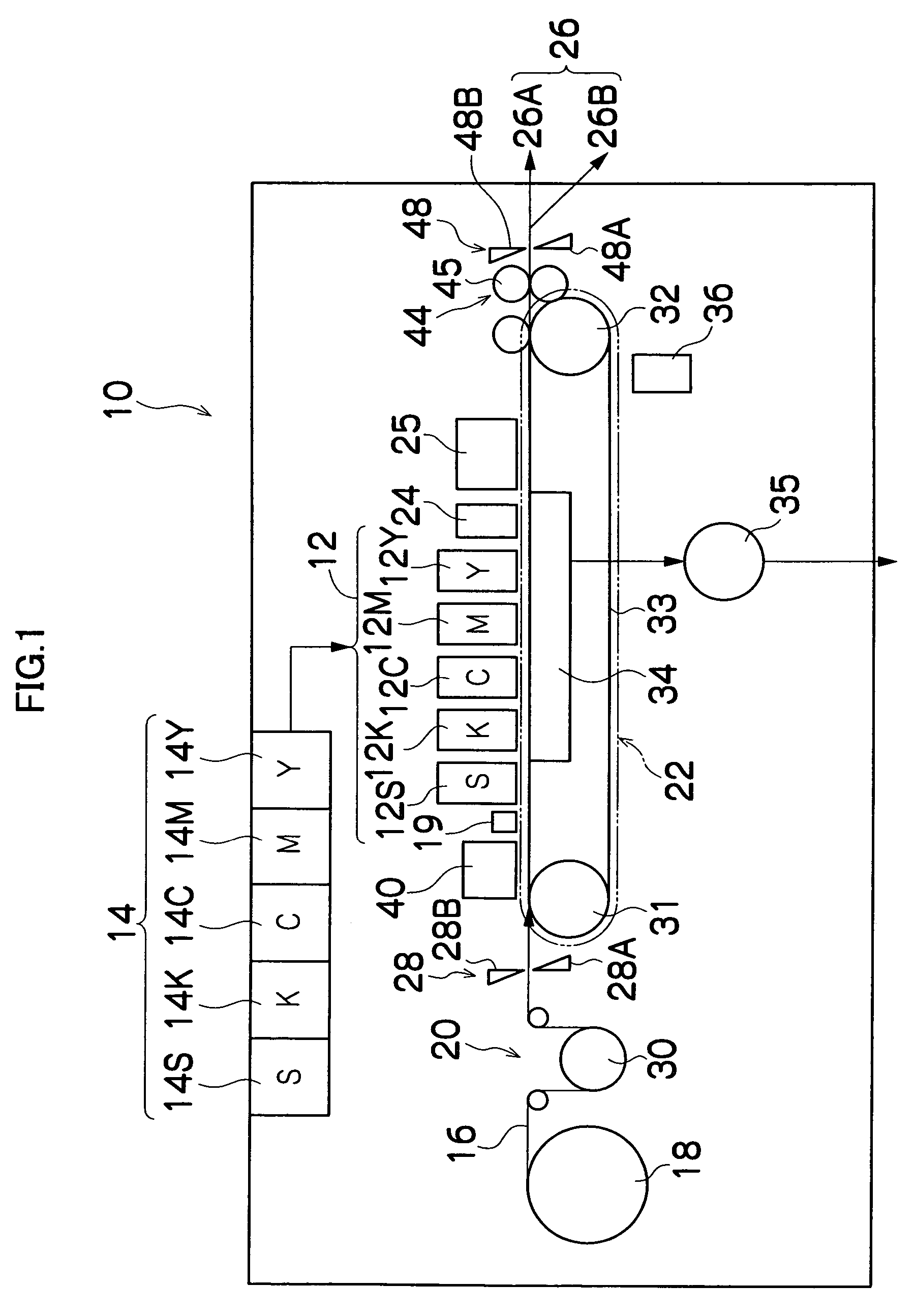
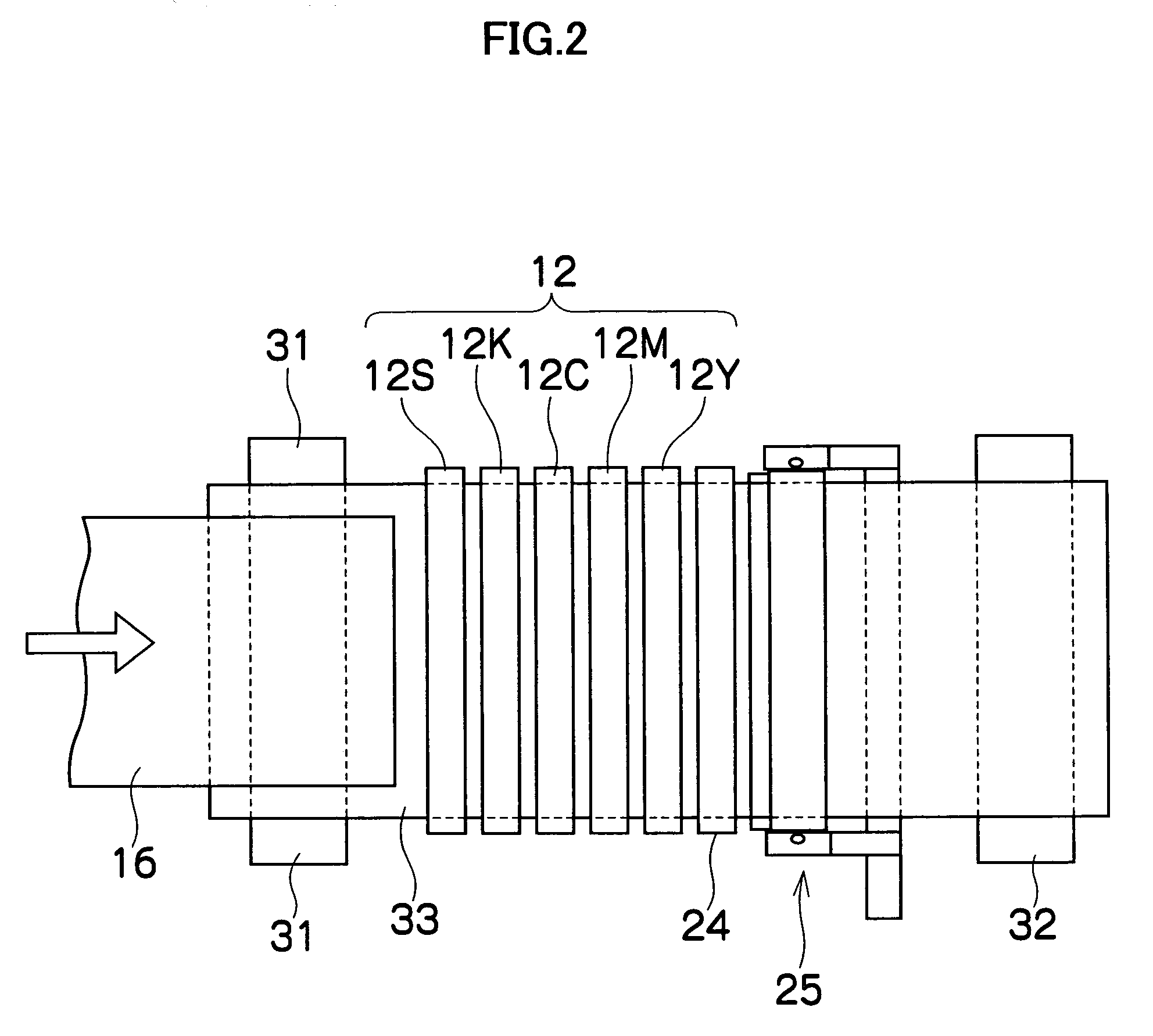
[0085]FIG. 1 is a diagram of the general composition of an inkjet recording apparatus according to an embodiment of the present invention. As shown in FIG. 1, this inkjet recording apparatus 10 comprises: a print unit 12 having a plurality of print heads 12K, 12C, 12M and 12Y provided for respective inks of the colors black (K), cyan (C), magenta (M) and yellow (Y), and a treatment liquid ejection head 12S, which ejects treatment liquid promoting the fixing of the ink by reacting with the ink (hereinafter, the print heads 12K, 12C, 12M and 12Y and the treatment liquid ejection head 12S are referred to generally as the heads 12A, 12K, 12C, 12M and 12Y); a storing and loading unit 14 which stores the color inks corresponding to the print heads 12K, 12C, 12M and 12Y, and the treatment liquid corresponding to the treatment liquid ejection head 12S; a paper supply unit 18, which supplies a recording medium 16; a recording medium determinat...

second embodiment

[0208]Next, an inkjet recording apparatus 300 according to a second embodiment of the present invention is described. In the inkjet recording apparatus 300, the recording medium 16 is observed, and the liquid removal capability of the absorbing roller 100 during liquid removal is controlled on the basis of the result of the observing operation. The present embodiment exemplifies a mode where the liquid removal capability of the absorbing roller 100 is controlled by altering the suction force of the suction device 108.

[0209]FIG. 14 is a principal schematic drawing showing the composition of the liquid removal unit 302 of the inkjet recording apparatus 300, and FIG. 15 is a principal block diagram showing the system composition of the inkjet recording apparatus 300. The overall composition of the inkjet recording apparatus 300 is similar to that of the inkjet recording apparatus 10 shown in FIG. 1, and here, a general description is omitted and those parts which are different to the i...


PUM


Abstract

The image forming apparatus comprises: an ejection head which ejects liquid onto a recording medium to form a desired image on the recording medium; a conveyance device which moves at least one of the recording medium and the ejection head so as to move the recording medium in a conveyance direction relatively to the ejection head; a liquid removal device which performs liquid removal to remove the liquid on the recording medium and is arranged on a downstream side of the ejection head in the conveyance direction; a determination device which determines a state after the liquid removal is performed by the liquid removal device; and a liquid removal control device which implements control to adjust a liquid removal capability of the liquid removal device according to determination results of the determination device.

Description

BACKGROUND OF THE INVENTION[0001]1. Field of the Invention[0002]The present invention relates to an image forming apparatus, and a liquid removal capability setting method, and more particularly, to an inkjet recording apparatus or other image forming apparatuses which form images of high quality by efficiently removing surplus liquid on a recording medium, and to a liquid removal method for same.[0003]2. Description of the Related Art[0004]In image forming apparatuses, such as inkjet recording apparatuses, an image is formed on a recording medium by using liquid ink in which coloring material and additives are mixed into a solvent, such as water, alcohol, or the like. Liquid (ink solvent) remains on the surface of the recording medium on which the image is formed, and this can be the cause of image degradation (image defects), rear-side image transfer, cockling, and the like. In an inkjet recording apparatus, it is necessary to swiftly remove the liquid remaining on the recording m...

Claims


Application Information

Patent Timeline
Patent Type & Authority Patents(United States)
IPC IPC(8): B41J2/165
CPCB41J3/44B41J11/002B41J11/0035B41J11/007B41J11/0085B41J11/009B41J11/0095B41J11/70B41J15/165B41M7/00B41J11/0022
Inventor INOUE, HIROSHI
Owner FUJIFILM CORP
Learn More