
Self diagnosing HVAC zone configuration

a self-diagnosing and hvac technology, applied in the field of air conditioning systems, can solve problems such as difficult diagnosis, complex systems, and difficulty in installation and maintenance, and achieve the effects of reducing the number of errors, and improving the diagnostic accuracy

Inactive Publication Date: 2009-04-07
CARRIER CORP
View PDF7 Cites 10 Cited by
  • Summary
  • Abstract
  • Description
  • Claims
  • Application Information

AI Technical Summary

Benefits of technology

The invention is about a protective circuit that can trip when the current through it exceeds a certain level. This circuit is connected in parallel with devices that are individually powered on a selective basis by an interconnected control system. When the protective device trips, the control system can determine which device was receiving power at the time that it tripped. This information is then provided to the user for diagnosing and repairing the problem. The protective device is of the self-healing type where it resets itself after a predetermined time period, with current then being restored to the operating system.

Problems solved by technology

As improved design and operational procedures for heating, ventilation and air conditioning (HVAC) systems are continually being provided for the benefit of users, such systems are typically becoming more complex and difficult to install and maintain.
Among some of the difficulties that occur are improper wiring of the various components and the related problems which are difficult to diagnose in complex HVAC systems.
In the event that one of the damper drive motors is connected improperly, a fault will occur in the system, but it is difficult to determine exactly where that fault has occurred.
Accordingly, the diagnosis and repair of the problem can be unduly complicated.

Method used


Image

  • Self diagnosing HVAC zone configuration
  • Self diagnosing HVAC zone configuration
  • Self diagnosing HVAC zone configuration

Examples


Embodiment Construction

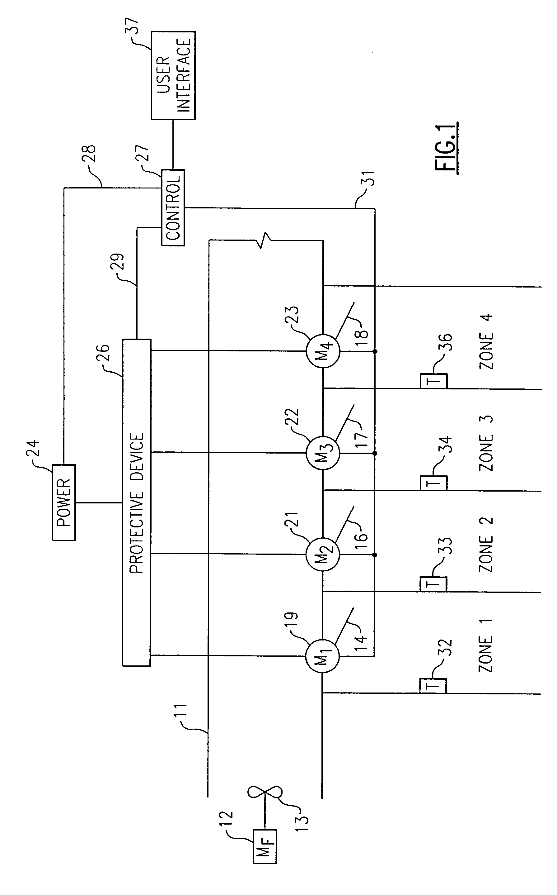
[0010]Referring now to FIG. 1 there is shown a simplified schematic illustration of a comfort system incorporating the present invention. A duct 11 carries conditioned air that is caused to flow by the motor 12 and associated fan 13, with the duct 11 extending over the four zones, Zone 1, Zone 2, Zone 3 and Zone 4. The zones have respective dampers 14, 16, 17 and 18, driven by respective motors 19, 21, 22 and 23. The amount of air flowing to respective zones is therefore dependent on the degree of openness of the respective dampers, and those positions are adjusted by operation of the respective motors which receive their power from a power source 24 by way of a protective device 26, one form of which may be a polythermal crystal (PTG). A control apparatus 27 receives power from a power source 24 by way of line 28 and communicates with the protective device 26 by way of line 29. The control 27 is also connected to the individual damper motors 19, 21, 22, and 23 by way of line 31.

[00...


PUM


Abstract

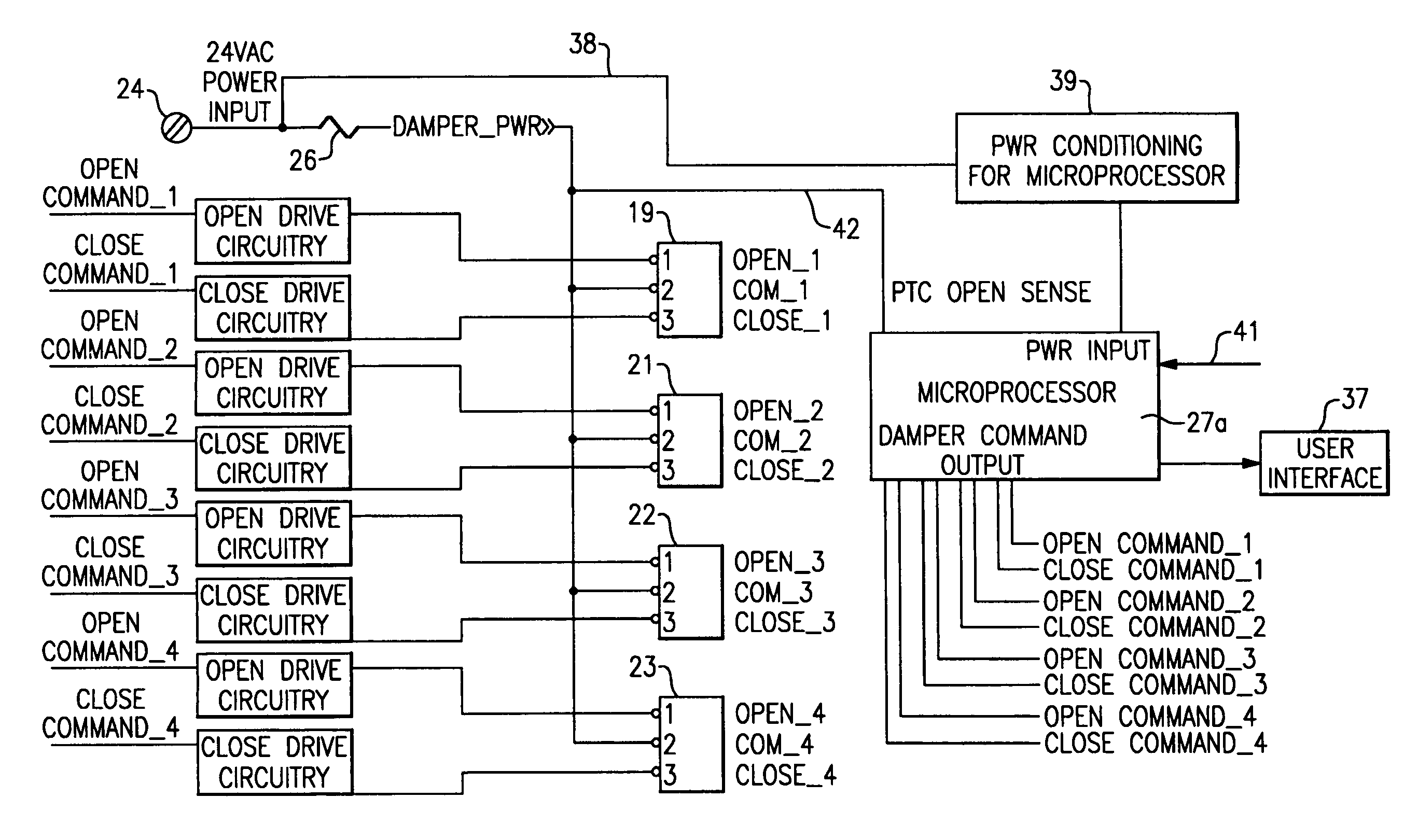
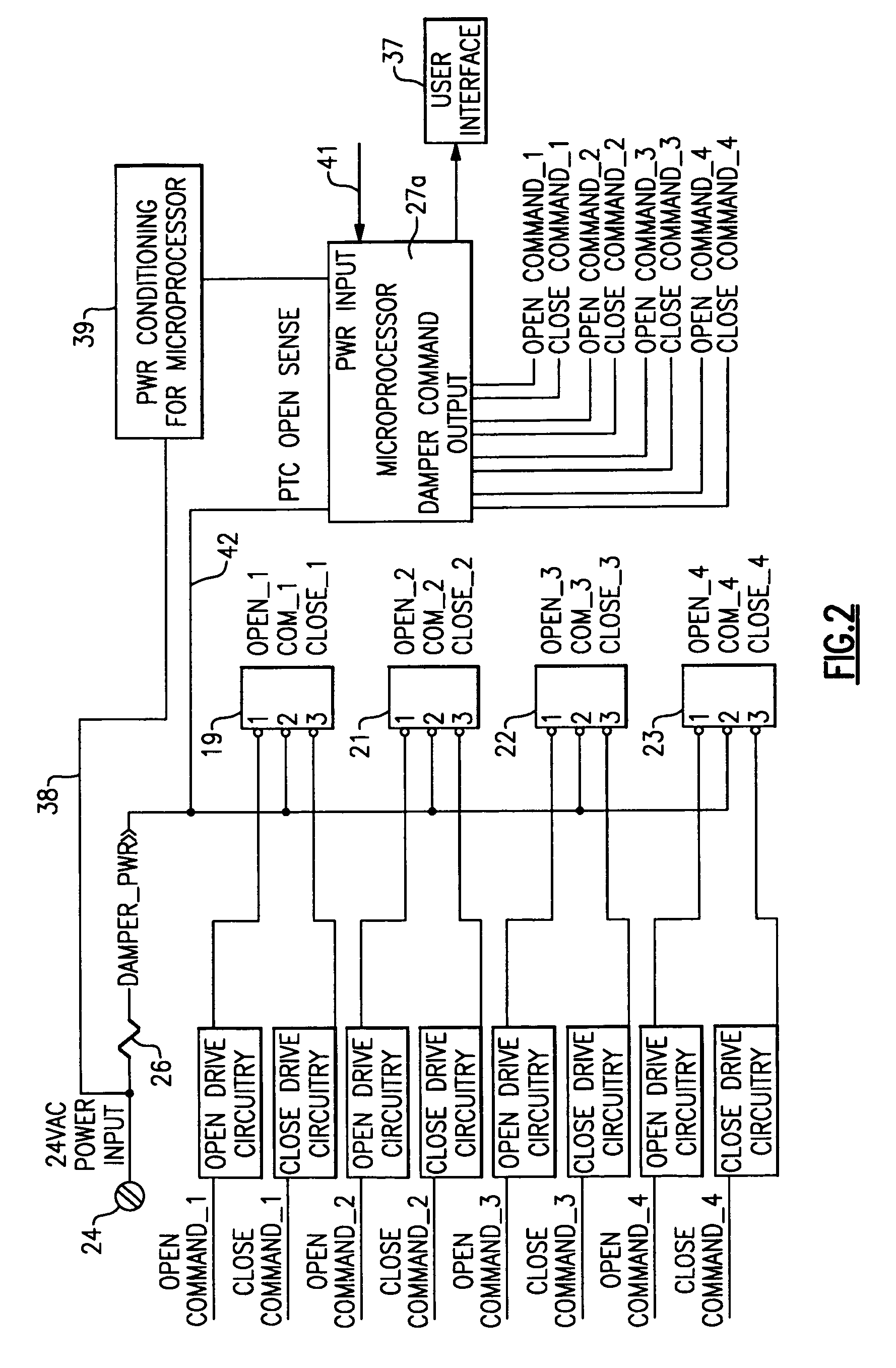
In a drive circuit in which a plurality of drive motors are connected to a power source through a protective device which trips when the flow of current is excessive, provision is made to detect which circuit or circuits were active at the time of the failure. A microprocessor is provided to both control the activation of each of the various circuits and to also sense which circuits were active at the time of the failure. Appropriate signals are sent from the microprocessor to a user interface so that proper diagnostic and repair action can be taken.

Description

BACKGROUND OF THE INVENTION[0001]This invention relates generally to air conditioning systems and, more particularly, to a method and apparatus for diagnosing faults in such a system having multiple drive motors.[0002]As improved design and operational procedures for heating, ventilation and air conditioning (HVAC) systems are continually being provided for the benefit of users, such systems are typically becoming more complex and difficult to install and maintain. Among some of the difficulties that occur are improper wiring of the various components and the related problems which are difficult to diagnose in complex HVAC systems. For example, in a multi-zone system, wherein it is desirable to introduce varying degrees of cooling or heating to various zones in a building, a plurality of drive motors are connected to position their respective dampers in a desired position so as to regulate the degree of cooling / heating in their particular zones. In the event that one of the damper d...

Claims


Application Information

Patent Timeline
Patent Type & Authority Patents(United States)
IPC IPC(8): G06F11/30G06F15/00G21C17/00H02P5/00
CPCF24F11/0086G06F11/0736G06F11/079F24F2011/0052F24F11/30F24F11/32F24F11/38F24F11/88
Inventor ENGLE, AARON
Owner CARRIER CORP
Learn More